
NOx Sensor Bracket Sheet Metal Work
This page explains how a small bent bracket controls sensor position in an exhaust stream, and why 0.25 mm of drift shows up as a fault code. It is written for design and manufacturing engineers who need to specify, quote, or debug this part. Read it to judge material, datum, and process choices before you release a drawing.
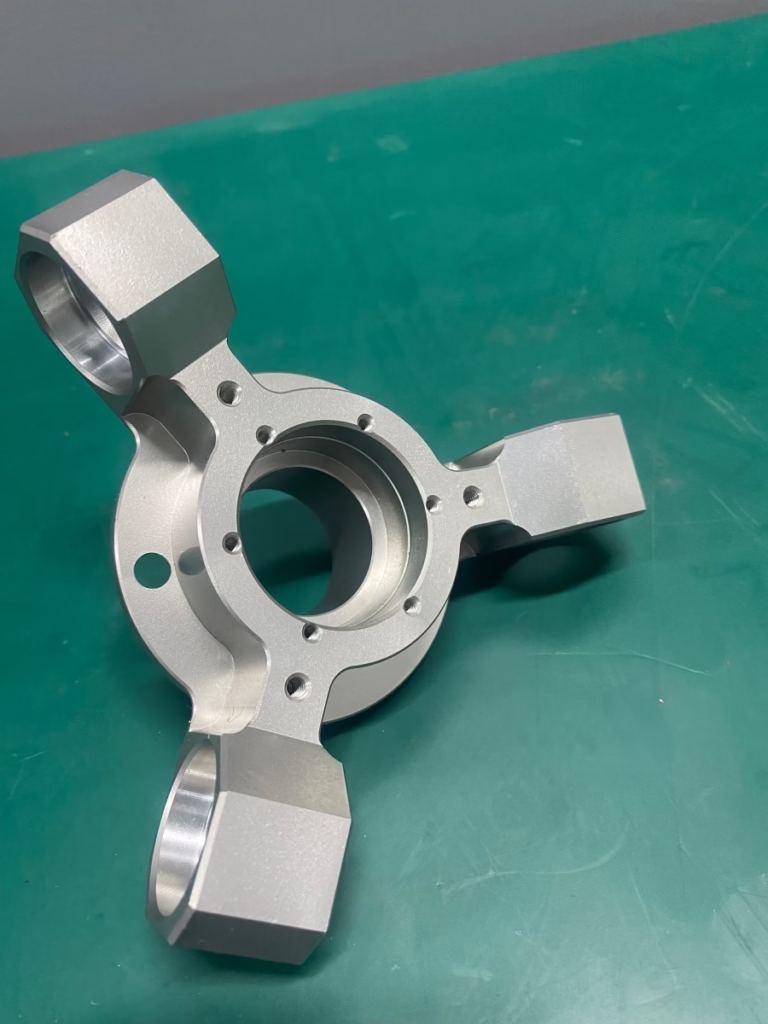
What the bracket actually does in the exhaust path
A NOx sensor bracket holds a probe at a fixed angle and depth inside an exhaust pipe. The probe tip must sit in the gas stream, not against the wall, and the connector end must stay clear of heat shields and wiring. Move the tip 2 mm inward and the sampled gas runs hotter and dirtier than the bulk flow. Move it 2 mm outward and the reading lags behind real conditions. Either way the ECU sees a number that does not match the engine state.
The bracket also carries the cable away from hot surfaces. A short, tight bend radius on the routing tab lets the wire rub against the pipe under vibration. That abrasion takes months to show up, then produces an intermittent open circuit. Good sheet metal work for this part means the routing tab is designed with the cable, not added after the sensor is chosen.
In a battery electric vehicle the exhaust stream only exists on range-extender or hybrid variants. The same bracket family still appears on thermal management lines and on some aftertreatment test rigs. The mechanical job is identical: keep a sensor at a known position through thermal cycling and vibration.
- 1Probe depthTip must sit in the gas stream, roughly 20–40% of pipe diameter.
- 2Boss angleTypically held within ±0.5° of the drawing nominal.
- 3RoutingCable bend radius kept above the wire maker's minimum.
Material choice: formability versus heat and corrosion
Most brackets in this family are made from 304 or 316 stainless, or from aluminized steel. Stainless resists salt spray and holds strength at high temperature. Aluminized steel costs less and takes a tight bend without cracking, but the aluminum–silicon layer can flake at a sharp bend line. On a 1.5 mm sheet, a bend radius below 1.5 mm is where that flaking usually starts.
Thickness is set by stiffness, not by strength. A bracket that is stiff enough at the sensor boss will not amplify vibration at the mounting flange. Going thinner to save weight often moves a resonance into the engine's operating band. Going thicker adds heat capacity and slows warm-up. Neither is free.
Welded studs, nuts, and gussets need a grade that welds without losing corrosion resistance. Projection welding of a stud onto 304 works well. Welding onto a heavily cold-worked bend line is where sensitization and cracking start. Keep welds at least 3 mm away from a formed radius when the drawing allows it.
- 1304 stainlessGeneral purpose, good weldability, 1.0–2.0 mm common.
- 2316 / 316LUse where chloride exposure or condensate is expected.
- 3Aluminized steelLower cost; keep bend radius generous to protect coating.
Datums, tolerances, and where the stack adds up
A typical bracket has a primary mounting flange, a sensor boss, and one or two secondary tabs for cable clips. The flange is usually datum A. The boss axis is the feature that matters most. If the boss is referenced to the flange, every bend between them contributes to the final angle error.
Bend angle tolerance of ±0.5° sounds tight until you multiply it across three bends. Two bends in the same direction can stack to 1°, which is enough to change probe depth at the tip. A common fix is to control the two critical bends and let the routing tab float within a looser band.
Hole position is the other trap. A slotted flange hole absorbs build variation in the pipe. A round hole does not. When the mating pipe is welded, allow 0.5–1.0 mm of slot travel so the bracket can be positioned at assembly without bending it into place. Bending a bracket to fit is how cracks begin.
- 1Datum APrimary mounting flange, the surface that seats on the pipe.
- 2Critical featureBoss axis angle, typically ±0.5°.
- 3Flange holesSlotted 0.5–1.0 mm where assembly variation is expected.
From flat blank to finished bracket
The route starts with a flat pattern. Bend allowance and K-factor decide whether the flat blank folds into a part that matches the drawing. For 1.5 mm stainless at a 1.5 mm inside radius, the neutral axis sits near 0.44 of thickness. Get that number wrong and the boss lands 0.3 mm off before any other error appears.
Laser cutting gives a clean edge and needs no tooling. It suits prototypes and low volumes. Stamping needs a die, so it only pays back above a few thousand pieces per year. Between those two, CNC punching with a standard tool set covers most mid-volume work.
Forming is where most of the variation lives. Press brake angle depends on material springback, which changes with grade and thickness. Stainless springs back more than mild steel. A first-article bend test on the actual heat lot is cheaper than chasing angle drift across a production run.
After forming, welded studs or a boss tube go on. Then the part is cleaned and finished. Passivation restores the chromium oxide layer on stainless after welding. Bead blasting gives a uniform matte surface and hides small scratch marks from handling.
- 1Laser cutBest for prototypes and low volume; no tooling cost.
- 2CNC punchMid volume with standard tools; fast setup.
- 3StampingPays back above roughly a few thousand parts per year.
Which sheet metal route fits which stage
Pick the row that matches your volume and change rate.
| Process | Best stage | Typical tolerance | Tooling cost |
|---|---|---|---|
| Laser cut + press brake | Prototype, 1–200 parts | ±0.1 mm on cut, ±0.5° bend | None |
| CNC punch + press brake | 200–5,000 parts | ±0.1 mm on cut, ±0.5° bend | Low, standard tools |
| Progressive stamping | Above ~5,000 parts/year | ±0.05 mm on form | High, dedicated die |
| Laser cut + weld fixture | Welded boss assemblies | ±0.2 mm boss position | Fixture only |
| Stamped + CNC finish | Tight boss bores | ±0.005 mm on machined bore | Die plus setup |
When to stamp and when to laser cut
Choose laser cut and press brake while the design is still moving or the volume is under a few thousand parts. Switch to a progressive die only after the geometry is frozen and annual volume justifies the tooling, because a die change costs more than years of laser time on a part this size.
Questions engineers ask before releasing the drawing
How tight should the boss angle tolerance be?
Most NOx sensor brackets hold the boss axis within ±0.5° of nominal. Tighter than that adds cost without helping the sensor, because the pipe weld itself moves the reference.
If the probe depth is the real concern, control the stack of bends that feed the boss and leave the routing tab looser.
Does stainless always beat aluminized steel?
No. Aluminized steel is cheaper and forms well if the bend radius stays generous. It fails when the coating cracks at a sharp bend and the base steel starts to corrode.
Use stainless where salt spray or condensate is expected. Use aluminized steel where cost dominates and the environment is mild.
Can the bracket be machined instead of formed?
Yes, for prototypes or very low volume. A machined bracket from 6061 or 304 bar avoids bend allowance and springback entirely.
It costs more per part and weighs more, so it rarely survives into production. It is a useful way to validate geometry before committing to a die.
What surface finish should we specify?
Passivation for welded stainless, because welding burns away the passive layer locally. Bead blasting if you want a uniform matte look and want to hide handling marks.
Powder coating works on the mounting flange but adds thickness that can affect seating. Keep coated surfaces out of the datum stack.
How do we stop vibration cracking at the flange?
Add a gusset or a formed rib between the flange and the boss wall. A flat bracket in bending has almost no stiffness against the mode that cracks welds.
Also check that the flange does not sit on a weld bead. A bracket forced flat against a weld is preloaded before the engine even starts.
What inspection data comes with the parts?
Raw material certificates, in-process checks, and a final inspection report on request. Critical dimensions are measured against the drawing datums.
For first articles we send a dimensional report with the measured values, not just a pass or fail stamp.
Send the drawing and get a manufacturability read
We review the flat pattern, bend sequence, and datum scheme, then quote in 12 hours. Uploads stay confidential and an NDA is available on request.
12-hour quote100% inspectionIATF 16949
More from the shop floor
We publish setup notes, tooling trials and inspection data from the factory floor.











