
CNC Wood Processing Center: How It Cuts, Holds and Where It Stops
A CNC wood processing center is a gantry or pod-and-rail machine that cuts, drills and routes sheet goods and solid wood under program control. This page explains the mechanics, the tolerance limits and the part shapes that actually suit the process. Written for engineers and buyers who need to judge a wood part before it goes to a shop.
In this article
- 1
- 2
- 3
- 4
- 5
- 6
- 7
What a CNC wood processing center does inside the cut
A CNC wood processing center removes material with a rotating cutter travelling along programmed paths. On a flatbed router the work sits on a vacuum table or a spoilboard; on a pod-and-rail machine the work is lifted on pods so the tool can pass underneath and cut the outline in one pass. The spindle runs a collet, so the same machine can hold a 6 mm down-cut spiral for laminate and a 12 mm compression bit for 18 mm melamine.
The dominant force in wood routing is not the cutting force. It is the tool pulling the panel upward off the table. Up-cut flutes lift the chip and the panel with it. That is why a down-cut or compression bit is specified whenever the top face is visible, and why vacuum zoning matters more than spindle power on thin panels. Lose hold-down and the part climbs the cutter.
Chip load sets the surface. For a 12 mm two-flute carbide bit in MDF, a feed of 4–6 m/min at 18,000 rpm gives a chip load near 0.15 mm per tooth. Too low and the edge burns and the tool rubs; too high and the panel chatters. Wood has no coolant, so heat leaves with the chip.
Rated tolerance belongs to the machine, not the material. A router positioning to ±0.05 mm still cuts wood that moves 0.3 mm overnight with humidity. Quote the drawing, then check the wood. MDF and plywood hold far better than solid oak across a long run.
- 1Vacuum zoningSeparate zones let small parts hold without covering the whole table.
- 2SpoilboardA sacrificial layer you resurface; it absorbs the final 0.2 mm of cut depth.
- 3Compression bitShears both faces of a veneered panel in one pass.
Which wood-based materials behave on a router
Sheet goods are the natural fit. MDF, HDF, plywood, particleboard and melamine-faced board are dimensionally stable, machine to a clean edge and hold a screw. A nested run of cabinet sides on 18 mm MDF is the classic job: outline, holes and hinge pockets in one setup, no repositioning error.
Solid wood is possible and often disappointing at volume. Grain direction changes the cutting force along the same edge, so a climb cut that works with the grain tears against it. Moisture swing moves the part after machining. Kiln-dried stock at 8–10 percent moisture content is the practical floor; anything wetter will move after it leaves the table.
Composites need different thinking. Carbon fibre and glass laminate dull carbide in minutes and produce abrasive dust that must be extracted at the cutter. Polycarbonate and acrylic cut cleanly but stress-crack around a tight radius, so keep the inside corner radius at least half the tool diameter.
Softer plastics cut like hardwood. ABS, POM and HDPE route well with two-flute carbide at moderate feed. They also burr, so a finishing pass with a 0.2 mm stepover removes the fuzz that a single roughing pass leaves behind.
- 1Best fitMDF, plywood, particleboard, melamine-faced board
- 2WorkableKiln-dried solid wood at 8–10 percent moisture content
- 3Needs careCarbon fibre, glass laminate, acrylic, polycarbonate
Flatbed, pod-and-rail and nested configurations
The flatbed router is the common shape. A moving gantry carries the spindle over a fixed table. Vacuum holds the sheet. It is fast on flat panels, cheap to tool and easy to load, but it cannot cut the underside without flipping the part. Every flip adds a setup and a datum error.
A pod-and-rail machine lifts the workpiece on pods, leaving the table clear for the cutter to pass below. That allows a full outline cut in one pass and access to all four edges. It suits a single large panel with a complex perimeter, not a nested run of forty small parts.
Nested-based routing is the volume answer. Parts are arranged inside a full sheet, cut in one program, then broken out. The trade is that every part shares the sheet datum, so one bad corner ruins the nest. Programming effort per part drops sharply as quantity rises.
A CNC wood processing center is not a machining center in the metal sense. There is rarely an automatic tool changer with forty pockets, and workholding is vacuum, not a vise. Treat it as a high-speed positioning system with a spindle, and the design rules become obvious.
- 1FlatbedFlat panels, nested runs, lowest cost per part
- 2Pod-and-railOne large panel, full outline, four-edge access
- 3NestedVolume runs, shared datum, high programming payoff
Tolerances, finish and where wood stops
Positioning on a good router is tight. Repeatability of ±0.05 mm is normal on a well-maintained machine, and a metal fixture plate cut on the same table can hold ±0.005 mm. Wood does not follow. It swells, it springs back after the cutter passes and it varies from board to board within one sheet.
Practical wood tolerances sit around ±0.2 mm on a routed outline and ±0.3 mm on a drilled hole. Below that, you are measuring the material, not the machine. If the drawing calls for ±0.05 mm on a wood feature, expect rework or a material change.
Surface finish is a function of tool and stepover, not of spindle speed alone. A 6 mm ball nose at 0.1 mm stepover leaves a finish that needs little sanding. The same tool at 0.5 mm stepover leaves visible scallops that no amount of speed will hide.
Where wood stops is where the tolerance, the edge quality or the volume no longer justify routing. Sealed, painted or laminated faces, tight bore alignment and metal inserts usually push the job toward a different process.
- 1Routed outline±0.2 mm is realistic on stable sheet goods
- 2Drilled hole±0.3 mm before the material dominates
- 3Metal fixture±0.005 mm on the same table, different ballgame
Design rules that keep a wood part routable
Keep inside corner radii at least half the cutter diameter. A 6 mm bit cannot cut a 1 mm internal corner; it leaves a radius and the mating part must match it. Draw the radius you will get, then design the joint around it.
Leave at least 8 mm of material between a pocket and the part edge on 18 mm MDF. Less than that and the wall flexes under cutting force, the vacuum seal breaks and the edge blows out. On thinner stock the minimum rises because the section is weaker.
Avoid deep narrow pockets. A pocket deeper than three times the tool diameter needs a long, thin cutter that deflects and chatters. If the feature is unavoidable, rough it with the largest tool that fits, then finish with a short reach tool at reduced feed.
Think about how the part is held. Every through-cut needs vacuum area underneath. Parts smaller than about 100 × 100 mm often need tabs or a sacrificial layer, because the vacuum cannot grip a small island once the outline is free.
- 1Corner radiusAt least half the cutter diameter
- 2Edge margin8 mm minimum between pocket and edge on 18 mm MDF
- 3Pocket depthKeep under 3× tool diameter where possible
- 4Small partsAdd tabs below roughly 100 × 100 mm
Wood parts that carry metal inserts and fixtures
Plenty of wood parts are not wood-only. A router-cut panel may carry threaded inserts, dowels, metal brackets or a machined aluminium frame. That is where a wood shop and a metal shop diverge, and where one supplier for both saves a setup.
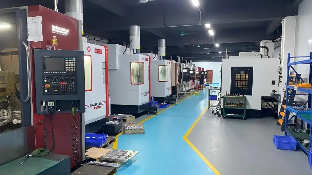
GreatLight machines wood-based panels on the same floor as metal fixtures. A routed MDF base and its aluminium mounting plate can share a datum, so the hole pattern lines up without a second fixture. Holes down to Ø2 mm in metal are drilled on the same 127-machine floor.
For parts that mix materials, the tolerance usually comes from the metal side. Set the wood feature at ±0.2 mm and the metal insert bore at ±0.005 mm, then check that the assembly still closes. Mixed-material parts fail on the interface, not on either material alone.
Finishing follows the same split. Anodizing, powder coating, bead blasting and laser marking apply to the metal side. Wood takes a sealer or a laminate. Laser marking with a minimum character height of 1.5 mm works on both, which is useful for part numbers on a mixed assembly.
- 1Shared datumWood panel and metal plate cut to one reference
- 2Metal bores±0.005 mm on the same floor
- 3MarkingLaser marking from 1.5 mm character height
Wood routing compared with three alternatives
Pick the process that matches the tolerance and the volume, not the one already on the floor.
| Process | Typical tolerance | Best for | Watch out for |
|---|---|---|---|
| CNC wood router | ±0.2 mm | Sheet goods, nested runs | Material movement after cut |
| Panel saw + edge bander | ±0.5 mm | Square cabinet boxes | No curves or pockets |
| Laser cutting | ±0.1 mm | Thin sheet, fine detail | Charred edge, burn smell |
| Waterjet | ±0.1 mm | Thick composites | Wet part, slow on wood |
When wood routing is the right call
If the part is flat, comes from sheet goods and the tolerance is ±0.2 mm or looser, route it and nest it. If the drawing needs ±0.05 mm, a sealed edge or a metal insert with tight alignment, machine the metal and treat wood as the cosmetic layer.
Questions engineers ask before releasing a wood part
Can a CNC wood processing center hold ±0.05 mm?
The machine can position that close on a stable fixture plate. Wood will not hold it. Moisture movement, springback and board-to-board variation push a routed wood feature to roughly ±0.2 mm.
If the drawing truly needs ±0.05 mm, the feature should be machined in metal and the wood used as a cover or spacer.
Why does the top face chip on veneered board?
The cutter is lifting the veneer instead of shearing it. An up-cut spiral pulls chips upward and takes the veneer with them.
Switch to a down-cut bit for a single-sided cut, or a compression bit when both faces are visible. Check that the panel is fully sealed to the vacuum zone before changing speeds.
How deep can a single routing pass go?
As a rule, no deeper than the cutter diameter in one pass on MDF. A 6 mm bit takes 6 mm, then a second pass.
Deeper passes raise cutting force and deflection, and the wall between pocket and edge starts to flex. Two lighter passes usually finish faster than one heavy pass with a cleanup.
Does humidity change the finished part?
Yes. Wood and MDF take on moisture and swell, mostly across the width of a panel. A part that measures correctly on the day of cutting can be 0.3 mm wider a week later in a damp room.
For parts that must stay stable, specify a sealed or laminated face on both sides, or move the critical feature to a metal insert.
What is the minimum part size that can be nested?
Around 100 × 100 mm is the practical floor with vacuum holding, because a smaller island cannot seal enough area once the outline is free.
Below that, add tabs that are cut by hand afterwards, or mount the parts on a sacrificial layer that stays under vacuum.
Can the same shop cut the wood and the metal bracket?
Yes, and it usually removes a setup. When the wood panel and the aluminium plate are machined to one datum, the hole pattern lines up without a second fixture.
Set the wood tolerance at ±0.2 mm and the metal bore at ±0.005 mm, then verify the assembly, not the individual parts.
Send the drawing, get a manufacturability read
Upload a panel or a mixed wood-and-metal assembly. We return a quotation and a free DFM analysis within 12 hours, with no minimum order quantity.
12-hour quote100% inspectionNo MOQ
More machining explainers from GreatLight
We publish setup notes, tooling trials and inspection data from the factory floor.











