
CNC Turning Center: Beginner's Guide
A CNC turning center holds a bar or blank in a chuck and turns it while a turret brings tools to the cut. This guide explains the mechanics, the machine configurations, and the limits that decide whether a part belongs on a lathe or a mill.
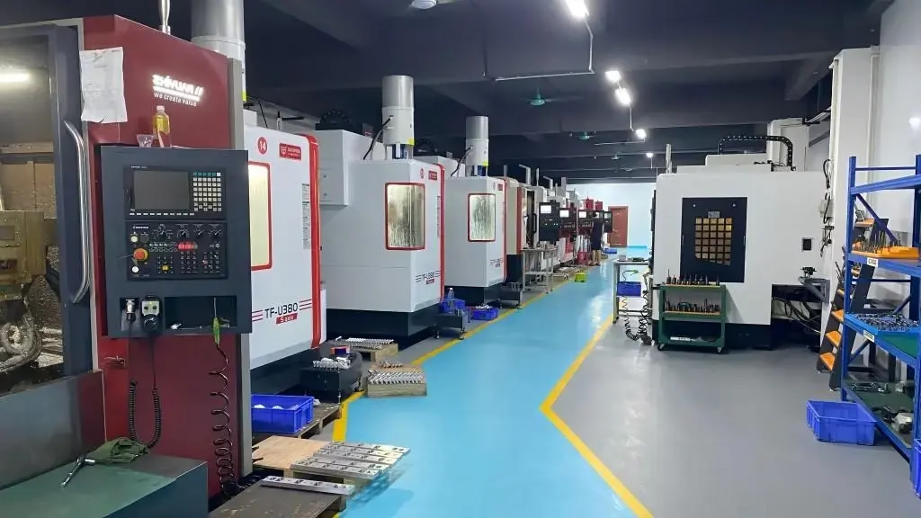
How a CNC turning center removes metal
A CNC turning center holds the workpiece in a chuck or collet and rotates it. The cutting tool stays mostly stationary and moves along the Z and X axes. The part spins, the tool feeds in, and material leaves as a continuous chip. That is the whole idea. Everything else on the machine exists to control where the tool tip goes.
Rotation speed is set in surface meters per minute, so the spindle rpm rises as the diameter gets smaller. Feed is set in millimeters per revolution, which means the chip load stays constant even as the diameter changes. On aluminium you might turn at 300–500 m/min with a 0.2–0.3 mm/rev feed. On 316 stainless, 120–180 m/min with 0.15–0.25 mm/rev is a sane starting point.
The turret indexes tools into position. A typical turning center carries 12 stations, and each station can hold a boring bar, a grooving insert, or a threading tool. Because the tool offsets are stored in the control, a single program can rough, finish, groove and thread a part without anyone touching the machine.
- 1Constant surface speedRpm rises as the tool moves toward center to keep cutting speed steady.
- 2Feed per revolutionChip load stays the same regardless of diameter.
- 3Tool offsetsEach turret station stores its own X and Z position in the control.
What a turning center can and cannot cut
A CNC turning center is designed around rotational symmetry. It is the right machine for shafts, bushings, fittings, spacers, valve bodies and threaded connectors. As a rule of thumb, if the part fits inside a circle when viewed from the end, a turning center can make it well and fast.
It is the wrong machine for flat plates, brackets with holes on multiple faces, or deep pockets with sharp internal corners. Those need a mill. Also, turning cannot produce a square shoulder with a truly sharp internal corner, because the insert has a nose radius, usually 0.4 mm or 0.8 mm. The corner will be rounded unless you add an undercut.
Long, slender parts are the classic problem. A shaft with a length-to-diameter ratio above about 6:1 will deflect unless it is supported by a tailstock or a steady rest. Below 3:1, you can usually turn unsupported. Between those, chatter becomes the limiting factor, not the insert.
- 1Good fitShafts, bushings, fittings, spacers, threaded parts.
- 2Poor fitFlat plates, multi-face pockets, sharp internal corners.
- 3Watch outL/D above 6:1 needs a tailstock or steady rest.
Main CNC turning center configurations
A two-axis turning center has X and Z only. It turns, faces, grooves and threads on the outside diameter. It is the cheapest configuration, the most common, and often the fastest for simple round parts. If your part has no features off the centerline, this machine is enough.
A turning center with live tooling adds driven tools in the turret, so the same machine can drill a cross hole or mill a flat while the part sits in the chuck. This removes a second setup, which matters when concentricity between the turned diameter and the cross feature is tight. It is slower than a dedicated mill for heavy milling.
A mill-turn center goes further. It has a B-axis or a swiveling head plus a subspindle, so the tool can approach the part from almost any angle and the back side can be machined without re-chucking. Complex valve bodies and medical implants often need this. The trade-off is programming time and machine cost.
- 12-axisOD turning, facing, grooving, threading. Fastest for simple parts.
- 2Live toolingAdds cross drilling and light milling in the same setup.
- 3Mill-turnMulti-angle work plus back-side machining without re-chucking.
Chucks, bar feeders and workholding
Most turning centers use a three-jaw hydraulic chuck. Jaws are bored to match the bar diameter, and clamping pressure is set so the part does not slip during roughing but does not collapse a thin wall. For thin-wall tubes, a collet or a mandrel works better because it spreads the clamping force around the circumference.
A bar feeder pushes stock through the spindle and lets the machine run unattended. Bar diameter is limited by the spindle bore, often 45–80 mm on a mid-size lathe. Parts longer than one bar length get cut off and face a new bar, which adds a few seconds per part. This is the cheapest way to run a high-volume turned part.
For castings, forgings or near-net blanks, the machine is loaded one piece at a time by a gantry or a robot. Cycle time is longer, but material waste is much lower. If your blank is expensive, such as titanium or Inconel, this is usually the right call.
- 1Three-jaw chuckStandard workholding. Bore jaws to match the bar.
- 2Collet or mandrelBetter for thin-wall parts that would deform under jaw pressure.
- 3Bar feederUnattended running, limited by spindle bore diameter.
Tolerances, finishes and what drives cost
Turning holds diametral tolerance well because the tool never leaves the cut between passes. At GreatLight, turned parts are routinely held to ±0.005 mm on critical diameters. That number is achievable on a rigid machine with the right insert and a stable setup. It is not achievable on a long, unsupported shaft.
Surface finish depends on feed, nose radius and cutting speed. A 0.4 mm nose radius at 0.1 mm/rev gives roughly Ra 0.8–1.6 μm. Finer feeds get you to Ra 0.2–0.8 μm but slow the cycle down. As-machined surfaces at Ra 1.6–3.2 μm are fine for most brackets and spacers.
Cost is driven by three things: how many setups, how much material is removed, and how tight the tolerance is. A part turned complete in one setup is far cheaper than the same part turned, then milled, then turned again. Reducing the number of setups usually saves more money than shaving a few seconds off the cycle.
- 1Tight tolerance±0.005 mm on critical diameters with a rigid setup.
- 2Fine finishRa 0.8–1.6 μm from a 0.4 mm nose radius at 0.1 mm/rev.
- 3Cost driversSetup count, material removal volume, tolerance band.
Turning center vs mill vs mill-turn
Use this table when deciding which machine should make a part.
| Machine | Best for | Typical tolerance | Limitation |
|---|---|---|---|
| 2-axis turning center | Round parts, OD and ID features only | ±0.005 mm on diameters | No off-center holes |
| Turning center with live tooling | Round parts with cross holes or flats | ±0.010 mm feature to feature | Light milling only |
| Mill-turn center | Complex parts, multi-angle, back side | ±0.005 mm on critical features | Higher programming cost |
| 3-axis mill | Plates, brackets, pockets | ±0.005 mm to ±0.010 mm | Slow on round parts |
| 5-axis mill | Freeform surfaces, one-setup complex parts | ±0.005 mm | Not economical for simple rounds |
Which machine should make your part
If the part is round and has no off-center holes, a 2-axis turning center is the cheapest and fastest route. If it needs cross holes or flats, add live tooling rather than a second setup. Choose mill-turn only when the part has features on several faces and concentricity between them is tight. For flat plates and pockets, a mill is always the right answer.
Common questions
Can a turning center drill holes on the side of a part?
Only if it has live tooling. A standard 2-axis turning center has no driven tools, so any cross hole has to be drilled on a mill in a second setup.
With live tooling, the turret spins the drill while the spindle indexes the part to the right angle. The hole position depends on spindle orientation accuracy, which is usually good to a few arc minutes.
What length-to-diameter ratio needs a tailstock?
Below 3:1, most parts turn without support. Between 3:1 and 6:1, you can often get away with a reduced depth of cut and a sharper insert.
Above 6:1, use a tailstock or a steady rest. Without support, the part deflects away from the tool and you get a tapered or barrel-shaped diameter.
Why does my turned diameter come out tapered?
The most common causes are tool wear, machine alignment, and part deflection. Check the insert first, because a worn nose radius pushes the tool away from the work.
If the insert is fresh and the taper is consistent, the tailstock may be out of alignment. A quick test is to turn a test bar and measure at both ends.
Which materials turn well?
Aluminium 6061 and 2024, brass C36000, and free-machining stainless 303 turn easily. These produce short chips and hold tolerance well.
Titanium Ti-6Al-4V, Inconel and 316 stainless are harder. They generate heat at the cutting edge, so speeds drop and coolant becomes essential. Tool life is shorter and cycle time is longer.
How is a turned part inspected?
Critical diameters are checked with micrometers, and features are verified against the drawing. GreatLight inspects 100% of parts before shipment, with reports available on request.
For first articles, a full dimensional report confirms every dimension on the print. Production parts get spot checks on the features that matter most.
Send a drawing, get a turning quote
Upload a STEP file and we will return a quotation with free DFM analysis within 12 hours.
12-hour quote100% inspectionNo minimum order quantity
More from GreatLight
We publish setup notes, tooling trials and inspection data from the factory floor.











