
CNC Surface Finishing Technology
Here is how a machined surface actually gets its final properties. We cover the mechanisms behind anodizing, plating, blasting and polishing, the Ra and tolerance they can hold, and when each finish is the wrong choice.
In this article
- 1
- 2
- 3
- 4
- 5
- 6
- 7
What CNC surface finishing technology changes at the surface
A machined surface is a record of the cutting process. Every pass of an end mill leaves a scallop, every feed rate leaves a pitch, and the tool nose radius sets the peak-to-valley height you can measure. CNC surface finishing technology removes, adds or reworks that layer. It changes three things at once: roughness, residual stress and chemistry.
Roughness is the one engineers quote first, usually as Ra. A standard milled finish from our 3-axis and 4-axis machines lands around Ra 1.6–3.2 μm. That is fine for a bracket nobody touches. It is not fine for a seal face, a sliding rail or an optical mount, where the peaks are what cause leakage, wear and scattered light.
Residual stress matters more than most drawings admit. Milling leaves tensile stress in the top 20–50 μm of the material. Polishing and blasting convert that layer into compressive stress or remove it entirely. That difference shows up as fatigue life, not as a number on a drawing.
Chemistry is the third lever. Anodizing grows an oxide from the aluminum itself. Plating deposits a different metal on top. Black oxide converts the steel surface in place. Each route gives different corrosion behavior, different dimensional change and different electrical conductivity.
- 1RemovalPolishing, lapping, blasting, abrasive flow.
- 2AdditionAnodizing, electroless nickel, zinc, silver, gold.
- 3ConversionBlack oxide and chromate layers on steel.
Machining parameters that decide the finish before finishing
No polishing step rescues a surface that was torn during cutting. The finish you can reach is set by spindle speed, feed per tooth, tool runout and coolant. Feed per tooth is the dominant term: at 0.05 mm per tooth you get visible scallops; at 0.01 mm per tooth the same tool leaves a much flatter profile.
Runout is the quiet killer. A tool holder with 0.02 mm of runout loads one flute harder than the others. That flute wears first and starts rubbing instead of cutting, which smears the material and buries debris in the surface. The part then needs extra polishing just to reach a mediocre Ra.
Coolant and chip evacuation decide whether the surface is cut or burnished. Aluminum 6061 and 7075 need plenty of flow to stop built-up edge. Stainless 304 and 17-4PH need it to control work hardening. Titanium TC4 needs both, plus lower surface speed, because heat stays in the cut.
On our 16 simultaneous 5-axis centers and 16 mill-turn centers, we set the finishing pass separately from the roughing pass. Roughing removes material at a high feed. The finishing pass uses a fresh tool, a small stepover and a stable spindle speed. That is how a milled face reaches Ra 0.8–1.6 μm before any secondary process.
Anodizing: growing oxide from the part itself
Anodizing is an electrochemical conversion. The aluminum part becomes the anode in an acid bath, and current drives oxygen into the surface. The oxide grows both outward and into the metal, roughly 50/50. That split is why a hardcoat layer does not simply sit on top of your dimensions.
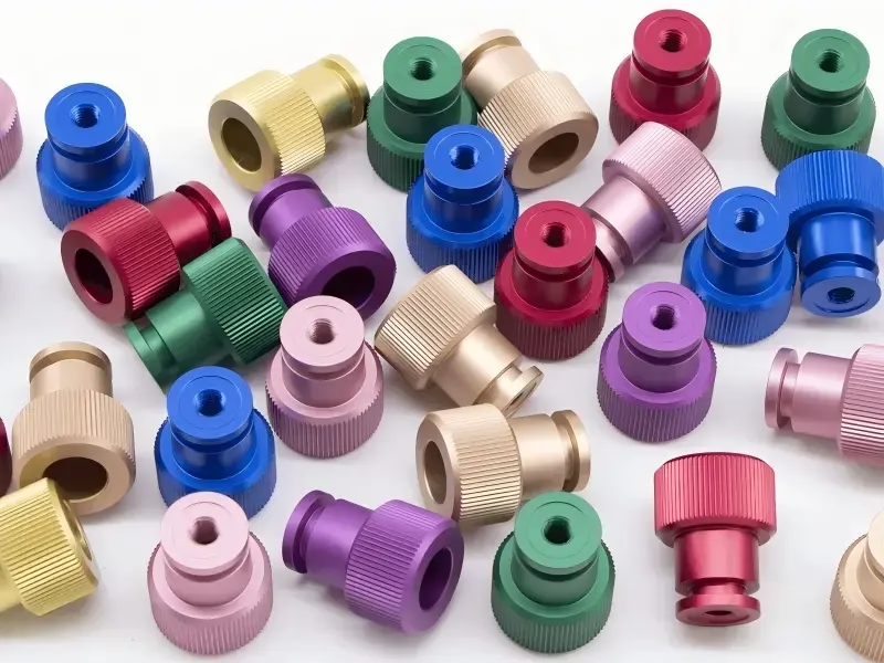
Type II clear or colored anodizing is typically 5–25 μm thick. Hardcoat anodizing runs thicker and harder, and it is the usual choice for wear surfaces on 6061-T6 and 7075. Conductive anodizing keeps selected areas electrically active, which matters on RF housings and grounding pads.
Three things go wrong often. First, sharp external corners build up oxide faster and can chip. Second, deep blind holes trap dye and rinse water. Third, tight holes shrink in a way that is hard to predict, so we mask critical bores or finish them after coating.
Aluminum choice changes the color result. 6061 and 6063 take dye evenly. 7075 turns darker and more yellow in clear anodize because of its copper content. If two mating parts must match, run them from the same alloy and the same lot.
Plating, blasting and polishing: where each one fits
Electroless nickel deposits without current, so it covers complex geometry evenly. That is its advantage over electroplated nickel, which builds thicker on edges and thin in recesses. Electroless nickel at 10–25 μm is a common answer for valve bodies, manifolds and any part with internal passages that must resist corrosion.
Zinc plating protects steel by sacrificing itself. Silver and gold plating are about contact resistance, not wear. On electronics housings we keep gold thickness low but uniform, because the connector interface is what matters, not the whole shell.
Bead blasting uses glass bead or ceramic media to knock down peaks. It produces an even matte that hides tool paths and gives anodize a consistent base. The risk is over-blasting: too much pressure rounds edges and can close small holes. On our parts we keep the nozzle moving and treat edges as a controlled loss.
Polishing is the only route to Ra 0.2–0.8 μm on most geometries. It works by removing material, so it cannot be used on a face that is already at final size. We polish before the final inspection pass and re-measure afterward when the drawing carries a tight tolerance.
- 1Tumbling and brushingDeburring and directional grain, low cost.
- 2Laser markingMinimum character height 1.5 mm for legibility.
- 3MaskingProtects threads, bores and grounding pads.
Tolerance, edge condition and the limits of finishing
Any finishing step that adds or removes material moves your dimensions. Hardcoat anodize can add 10–25 μm per surface, which is 20–50 μm on a diameter. On a ±0.005 mm feature that is the entire tolerance band. The fix is either to mask the feature or to machine it undersize by the known coating build.
Edges are the second limit. Coating builds on a sharp corner and thins on a radius, so a hard anodized edge can chip under load. We deburr and add a small chamfer or radius before coating whenever the drawing allows it. This is a geometry decision, not a finishing decision.
Surface finish and tolerance pull against each other. A mirror polish on a large flat face tends to crown or dish the surface by a few micrometers. On a seal face that is acceptable. On a precision datum it is not. That is when we polish selectively and keep datums as machined.
Materials set hard boundaries too. Magnesium AZ31B and AZ91D need dedicated pretreatment and cannot share a line with aluminum. Titanium and Inconel take longer in any abrasive step. Copper alloys polish quickly but tarnish fast, so they usually get a plated or lacquered top layer.
How we sequence finishing on a real part
- 1Read the drawingList every note: Ra, coating type, thickness, masking zones, datums.
- 2Fix the machining passSet feed per tooth and stepover to reach Ra 0.8–1.6 μm before secondary work.
- 3Deburr and radiusBreak sharp edges to 0.2–0.5 mm unless the drawing forbids it.
- 4Mask critical featuresThreads, dowel holes, bores and grounding pads get masked or plugged.
- 5Apply the finishAnodize, plate or blast to the specified thickness range.
- 6Re-measureCheck coated dimensions and Ra, not just the pre-coat numbers.
- 7Inspect and pack100% inspection before shipment, reports on request.
Finish comparison by mechanism and typical result
Ra values are what the process typically reaches, not a guarantee on every geometry.
| Finish | Mechanism | Typical thickness | Best for |
|---|---|---|---|
| As machined | Cutting only | 0 μm | Brackets, hidden faces |
| Bead blasting | Abrasive removal | 0 μm | Uniform matte, tool mark hiding |
| Polishing | Abrasive removal | 0 μm | Seal faces, optical mounts |
| Clear anodize | Oxide growth | 5–15 μm | Housings, mild corrosion |
| Hardcoat anodize | Oxide growth | 20–50 μm | Wear surfaces, sliding parts |
| Electroless nickel | Metal deposition | 10–25 μm | Uniform coverage, tight bores |
| Black oxide | Chemical conversion | 1–3 μm | Steel tooling, low build-up |
| Powder coating | Polymer deposition | 60–120 μm | Outdoor frames, thick film |
Pick the finish from the failure mode, not the catalog
If the part fails by corrosion, choose anodize or plating. If it fails by wear or friction, choose hardcoat or polishing. If it fails by electrical contact, choose gold or silver plating with masked pads.
Questions engineers ask before releasing a finish
Does anodizing change my dimensions?
Yes. The oxide grows both outward and into the aluminum, roughly half each way. A 20 μm hardcoat layer adds about 10 μm outward per surface, so a diameter grows by roughly 20 μm total.
On a ±0.005 mm feature, machine undersize by the known build or mask the surface. We decide this before the finishing pass, not after.
Can I get Ra 0.2 μm on a milled face?
Only with a secondary polishing step. Milling alone on our machines reaches Ra 0.8–1.6 μm on a stable setup.
Polishing removes material, so a face already at final size cannot be polished without rework. Keep polishing for faces with material allowance.
Which finish works best for stainless 304 and 17-4PH?
Stainless does not anodize. It takes bead blasting, polishing, electroless nickel, passivation or black oxide depending on the requirement.
17-4PH polishes well and holds a fine Ra. 304 work hardens during cutting, so the machining pass matters more than the finishing pass.
How does bead blasting affect an anodized surface?
Blasting sets the base texture. A light blast gives a fine satin look under clear anodize; a heavy blast gives a coarser matte and can round edges.
We keep the blast pressure and nozzle speed fixed across a batch so the texture stays consistent from part to part.
Do you need an NDA for finishing work?
Uploads are secure and confidential, and we sign an NDA on request before reviewing drawings.
Finishing notes often reveal function, so we treat them as design data, not just process data.
What is the smallest marking you can laser?
Minimum character height is 1.5 mm. Below that, legibility drops fast on anodized and blasted surfaces.
If the part needs a tiny mark, we test on a scrap piece from the same material and finish first.
Send the drawing, get a finishing plan
We review your finish notes, flag masking and tolerance conflicts, and quote within 12 hours. From one prototype to 10,000+ part runs, no minimum order quantity.
12-hour quote100% inspectionNDA on request
More from the shop floor
We publish setup notes, tooling trials and inspection data from the factory floor.











