
CNC Machining PA: What the Process Can and Cannot Hold
A plain explanation of how CNC machining works, what tolerance and finish are realistic on aluminum, stainless and titanium, and where the process stops being the right answer. Written for design and sourcing engineers who need to judge a quote, not read a brochure.
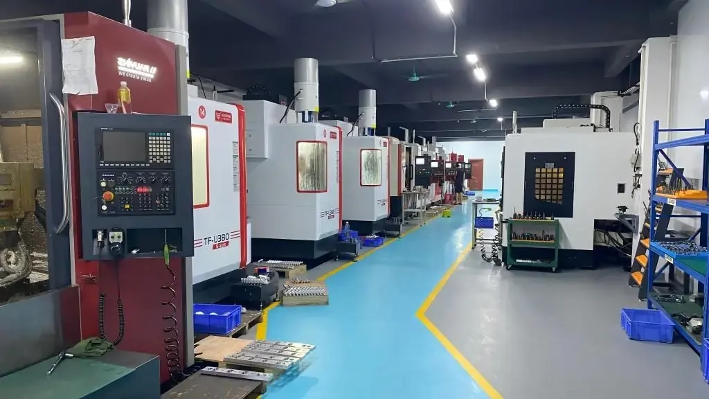
How CNC machining in PA removes material
CNC machining is subtractive. A rotating cutter or a turning tool meets a solid block, and the machine follows a program that defines where the tool goes, how fast it spins and how quickly it feeds. Nothing is molded or layered, so the part inherits the mechanical properties of the stock instead of a new set of properties from a melt.
The program is the difference from manual work. On a manual mill, the operator turns a handwheel and watches a dial. On a CNC machine, the same move is a line of G-code with a commanded position, and the control loop holds that position thousands of times per second. Repeatability comes from the loop, not from the operator's eye.
That repeatability has a hard limit. The machine holds position within its own accuracy, but the cutter deflects, the material springs back, and heat moves the part. A tight tolerance on a thin wall is a different problem from the same tolerance on a solid block. Good shops quote those two jobs at different prices because the risk is not the same.
CNC machining PA covers milling, turning, drilling and grinding on the same floor. A part that needs a milled face, a bored bore and a threaded hole can often run in one setup family instead of three handoffs, which is where lead time and tolerance stack both improve.
What tolerance and surface finish are realistic
Tolerance is a promise about where a surface ends up. ±0.005 mm is achievable on a rigid setup with a stable material and a sharp tool. It is not achievable on a 3 mm tall fin in aluminum that vibrates before the finish pass starts. The number on the drawing has to match the geometry it sits on.
Surface finish moves with the same logic. As-machined surfaces sit around Ra 1.6–3.2 μm. A high-quality finish lands at Ra 0.8–1.6 μm with a controlled finishing pass. Fine finishes at Ra 0.2–0.8 μm need slower feeds, lighter depths of cut and often a second operation, so they cost more per part than a cosmetic spec suggests.
Material pushes back. Aluminum 6061 cuts freely and holds a good finish. 304 stainless work-hardens at the cut and pulls heat into the tool. Titanium TC4 (Ti-6Al-4V) needs lower surface speeds and more coolant, and thin sections move after the clamps come off.
A useful habit: put the tight tolerance only on the features that touch another part. Datum faces, bearing bores and sealing surfaces earn ±0.005 mm. Clearance holes, cosmetic edges and brackets usually do not, and loosening them cuts cycle time without hurting function.
Why five-axis setups cut error and cost
Every time a part comes off the table and goes back on, the origin moves a little. Fixture wear, chip seating and clamp pressure all add a few microns. A three-axis part with six faces may need four or five setups. A five-axis machine reaches those faces with the tool and the table, so the count drops.
Fewer setups mean less stack-up. If each flip adds ±0.01 mm of position error, five flips can eat a ±0.05 mm feature tolerance before a single cut is wrong. Five-axis work keeps the part on one origin, which is why complex housings and impellers often come out cheaper on a five-axis machine than on three three-axis runs.
Five-axis is not free. Programming takes longer, the machine hour rate is higher, and a badly planned toolpath can leave witness marks on a surface you wanted to keep. For a flat plate with four holes, three-axis is faster and cheaper. For a part with angled ports or undercut ribs, five-axis pays for itself.
The practical split: 16 simultaneous five-axis machining centers handle contoured and multi-face work; 27 three-axis machines handle prismatic parts with simple geometry. Sending a simple part to a five-axis machine usually raises the price without improving the part.
Material choices and what they do to the cut
Aluminum covers most prototype and enclosure work. 6061-T6 machines cleanly, takes anodizing well and keeps a stable dimension after machining. 7075 is stronger but less forgiving of sharp internal corners. 2024 has better fatigue behavior and worse corrosion resistance unless it is coated.
Stainless grades split by behavior. 303 is the free-machining grade and produces a good finish quickly. 304 and 316 resist corrosion better and machine harder. 17-4PH (SUS630) can be aged after machining to raise strength, but the heat treatment moves dimensions, so finishing stock has to be planned in.
Steel and titanium follow the same rule: harder material, slower cut, more tool wear. 4140 and 4340 need a pre-hardened or annealed strategy decided before the first operation. Inconel and magnesium AZ31B / AZ91D sit at the two ends of the difficulty range and both need a shop that has run them before.
Plastics are a different set of problems. POM and PEEK hold tolerance well. ABS and PP are soft and can bow after clamping. Carbon fibre eats tool edges and needs dust control. A shop that machines mostly aluminum may not have the extraction and tooling for carbon fibre, and that gap shows up in the first article.
Inspection, documentation and where the risk sits
A machined dimension is only as good as the measurement behind it. Calipers read to roughly ±0.02 mm in a trained hand. A micrometer or a bore gauge does better on a specific feature. A CMM gives a full picture of position and form, and it is the tool that matters when a tolerance sits below ±0.01 mm.
Process control is what keeps a run inside tolerance. Raw material comes in with a certificate. In-process checks catch drift before the part is finished. Final inspection confirms the drawing before the box is closed. When those three steps are in place, a shop can report a qualification rate of 99.99% without inspecting every feature on every part.
Documentation matters more than the number in some industries. Aerospace, medical and automotive programs want material certificates, inspection reports and traceability that ties a part back to a heat number. Ask for the report format before the run, not after, because reformatting data later costs days.
The risk sits in the interface between design and process. A drawing that calls out a tight tolerance with no datum, or a finish spec with no direction, forces the shop to guess. Every guess is a place where the first article comes back with a note instead of a shipment.
Which process route fits the part
Match the geometry to the method before you ask for a price.
| Part feature | Best route | Why |
|---|---|---|
| Flat plate, 4 holes, 2 faces | 3-axis milling | Simple orientation, fast cycle, low setup count |
| Angled ports, undercut ribs | 5-axis milling | One origin, no re-fixture error |
| Shaft with thread both ends | Mill-turn or turning | Round work stays on axis, no re-chucking |
| Thin wall under 1 mm | 3-axis with support | Five-axis reach adds no value on a flexible wall |
| Tight bore ±0.005 mm | Boring on a rigid setup | Boring bar beats an end mill for roundness |
| Fine finish Ra 0.2–0.8 μm | Separate finishing pass | Slow feed, light depth, second operation |
| One-off prototype | Rapid prototyping | Geometry check before hard tooling |
| 10,000+ identical parts | Die casting plus machining | Casting carries shape, machining carries tolerance |
When to machine and when to cast
If the part is complex, low volume, or the geometry may still change, machine it. If the shape is stable and the annual volume runs into thousands, cast the blank and machine only the critical faces, because that is the point where the per-part cost drops below a fully machined part.
Questions engineers ask before the first cut
How tight a tolerance can CNC machining hold on a normal part?
On a rigid setup with stable material, ±0.005 mm is realistic. That number applies to a specific feature, not to the whole part. Thin walls, long unsupported bores and deep pockets usually need a looser callout or a support feature added to the design.
If a feature truly needs ±0.005 mm, say so on the drawing and give it a datum. The shop can then plan the setup, the tool and the inspection around it instead of guessing which dimensions matter.
Does five-axis machining always cost more than three-axis?
The machine hour rate is higher, but the total part cost is often lower when the part has angled faces or needs several orientations. Re-fixturing adds labor, setup time and position error. Five-axis removes those three costs at once.
For prismatic parts with simple geometry, three-axis is still the cheaper route. The decision should follow the geometry, not the machine list.
What surface finish should I specify?
Start from function. A mating face or a sealing surface may need Ra 0.8–1.6 μm. A bracket that only needs paint can run at Ra 1.6–3.2 μm as machined. Fine finishes at Ra 0.2–0.8 μm are worth specifying only where friction, sealing or appearance demands them.
A finish callout with no direction, such as a general note on the drawing, is hard to inspect and hard to price. Put the finish on the faces that need it.
How do I know a shop can hold the tolerance it quotes?
Ask what they measure with and how often. A shop with a CMM, a bore gauge set and an in-process check plan can show how it holds a dimension across a run. A shop that only names a machine model is telling you less.
Ask for the inspection report format before the run. If the report cannot express your datum scheme, the measurement will not prove the part either.
When is CNC machining the wrong process?
When the part is a thin shell with uniform wall, when the annual volume is high and the shape is stable, or when the geometry is a lattice that a cutter cannot reach. Die casting, sheet metal fabrication, vacuum casting and 3D printing each cover part of that ground.
Machining is also a poor fit when the design is still moving every week. Prototype routes exist for that stage, and switching to machining after the shape settles saves money.
What information makes a quote accurate?
A 3D file plus a drawing with datums, tolerances, finish callouts and material grade. Add quantity, target date and any certification requirement. With those inputs, a quotation and a DFM analysis can come back within 12 hours.
Uploads stay confidential, and an NDA is available on request when the program needs one.
Send the drawing, get the cut plan
Upload a 3D file and drawing, and we return a quotation with a DFM analysis within 12 hours. No minimum order quantity, from one prototype to 10,000+ part runs, with 100% inspection before shipment.
12-hour quote100% inspectionNo MOQ
More process notes
We publish setup notes, tooling trials and inspection data from the factory floor.











