
CNC Machining NC: How Numerical Control Actually Cuts Metal
This page explains what numerical control does inside a CNC machine, which part features it suits, and where the process runs out of room. Written for design engineers and buyers who need to judge a part before they send it out.
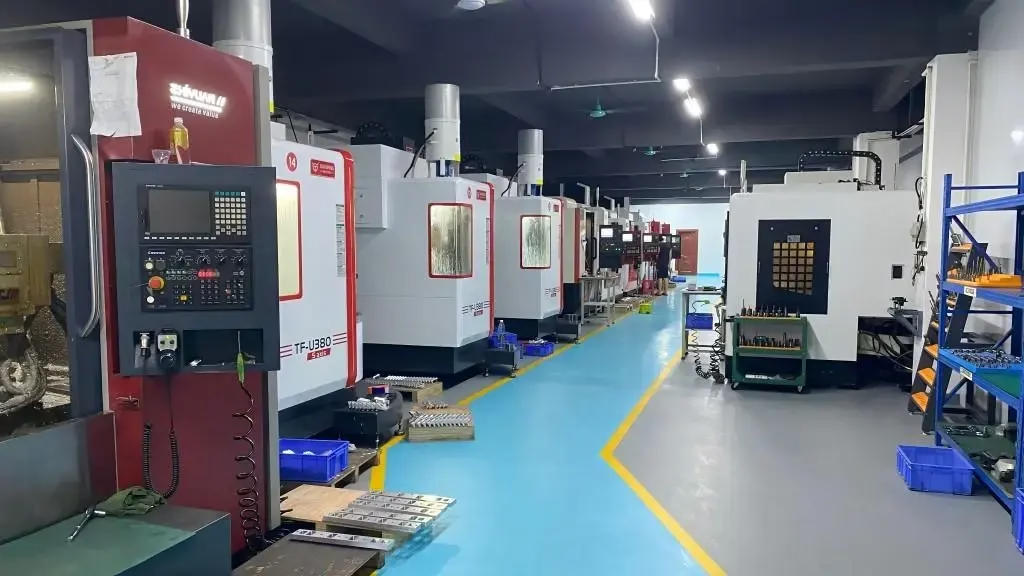
What CNC Machining NC Means on the Shop Floor
NC stands for numerical control. A program made of coordinates tells the machine where the cutting edge should be, and the machine moves the slide to that point. Early NC machines read punched tape. Modern CNC adds a computer that reads the same coordinate data, applies cutter compensation, and adjusts feed and speed while the tool is in the cut. The letters still describe the same idea: the tool path comes from numbers, not from a handwheel.
On a three-axis mill, the table moves in X and Y and the spindle moves in Z. A CNC machining NC program for that machine is mostly a list of straight moves and arcs, plus tool changes and spindle commands. The operator still chooses the fixture, the tool, and the depth of cut. The program decides position and feed rate. That split matters when a part goes wrong, because the fix may sit in the CAM file or in the vise.
The control reads feedback from encoders on each axis. It compares the commanded position with the measured position many times per second and corrects the difference. That closed loop is why a machine can hold ±0.005 mm on a good day and still drift when the shop warms up in the afternoon. Thermal growth moves the ball screw, and the control has no idea the screw got longer.
Feed and speed come from the material, not from habit. Aluminum 6061 cuts at high surface speed with a two or three flute carbide tool. Titanium TC4 and Inconel want lower surface speed, more coolant, and a rigid setup. Push either one past its range and the tool wears on the flank instead of the tip, which shows up as a size drift across the run.
Where CNC Machining NC Fits and Where It Does Not
CNC machining NC suits parts with defined geometry, moderate volume, and tolerances that need to hold across every unit. Brackets, housings, manifolds, heat sinks, bone plates, and engine components all fit. The process cuts metal, plastic, and composite stock, so material choice rarely blocks a design. GreatLight runs aluminum 6061 and 7075, stainless 303 and 17-4PH, tool steel, brass C36000, and titanium TC4 on the same floor.
It is a poor fit when the part is a thin shell with large unsupported spans. A 0.8 mm wall on a 200 mm panel will move when the vise releases it, no matter how slow the finishing pass runs. It is also a poor fit for a part with internal channels that no tool can reach. Deep cross-drilled holes, blind undercuts, and closed cavities need a different process or a redesigned feature.
Volume changes the answer too. One prototype and ten thousand parts can come off the same machine, but the cost curve differs. Setup and programming spread over the run. At low volume the setup dominates. At high volume a casting or a die-cast tool often wins on unit cost, and machining moves to the critical faces only. GreatLight runs both, so we can tell you where the crossover sits for your part.
Surface finish is a boundary of its own. As-machined faces land at Ra 1.6–3.2 μm. A careful finishing pass reaches Ra 0.8–1.6 μm, and lapping or polishing can reach Ra 0.2–0.8 μm. If the drawing calls for a mirror finish on a large area, the cost is in the hand work, not in the spindle time. Ask whether the whole face needs it or only a seal land.
Why the Fixture Decides the Tolerance
A machine that holds ±0.005 mm on a test block will not hold it on a part that rings like a bell. The workpiece and the fixture form one elastic system. Clamp a thin flange at four points and the middle bows. Cut it flat, release the clamps, and it springs back. The control did its job. The setup did not.
Five-axis work reduces the number of setups. A part that would need four sides on a three-axis machine can often be finished in two setups on a five-axis center, which removes the re-datum error each time the part is flipped. That is the main reason to pay for five axes on a complex housing. The rotary table on our machines is Ø400 mm, which sets a practical limit on part swing.
Datums carry across a process. If the first setup is built off a rough casting face, every later dimension inherits that error. We face the datum in the first operation, then build the rest from it. Leave a datum note on the drawing, and mark the faces you care about. A model with no datum callout forces the programmer to guess, and guesses are where size creep starts.
Stock removal order also matters. Roughing removes most of the material and releases residual stress from rolled plate. If you finish in the same setup, the part can bow overnight. A rough, a stress-relief pause, and a finish pass costs more but holds size on a long thin part. For a part with a 4:1 length-to-width ratio, it is usually worth it.
How We Prove the Numbers After the Cut
A tolerance on a drawing is a claim until someone measures it. We check raw material certificates on arrival, monitor size during the run, and inspect 100% of parts before shipment. Reports are available on request. For a first article, the report covers every dimension the drawing controls, not just the tight ones.
CMM inspection is the usual route for position and profile callouts. For a bore or a shaft, a micrometer or a bore gauge reads faster and is just as honest. The instrument has to match the tolerance. A caliper with 0.02 mm resolution cannot sign off a ±0.005 mm feature, and a report built that way is not evidence.
In-process checks catch drift before the run ends. A tool that has cut 300 parts will not hold the same size as a fresh one. We measure at set intervals and comp the tool when the trend shows up. That is how a 10,000 part run stays inside tolerance without sorting at the end.
The qualification rate across our floor is 99.99%. That number comes from inspection data, not from a marketing slide. When a part falls outside, we tell you what happened and what we changed. A supplier who reports zero problems on a hard part is not measuring the hard part.
Material Choice Changes the Cut
Aluminum is the easy case. 6061-T6 machines fast, holds a good finish, and takes anodizing well. 7075 is stronger but gummier, so it needs sharper tools and more coolant. Thin walls in 7075 distort more than in 6061 because the strength that helps the part also fights the cutter.
Stainless 303 is free-machining and behaves well. 304 and 316 work-harden if the tool rubs instead of cuts, so keep the feed up and never dwell. 17-4PH in the H900 condition is hard enough to shorten tool life and is usually machined in the annealed state, then aged. If your drawing calls for H900, say so on the purchase order.
Titanium TC4 and Inconel sit at the other end. Low thermal conductivity pushes heat into the cutting edge. Tool life is short, cycle time is long, and the setup has to be stiff. A 0.5 mm depth of cut that works in aluminum will chatter in Inconel. These materials are worth the cost when the part sees heat or load, and hard to justify when it does not.
Finishing follows the material. Anodizing in clear, color, or hardcoat suits aluminum. Electroless nickel, zinc, silver, and gold plating cover steel and copper alloys. Powder coating and black oxide handle larger steel parts. Bead blasting, tumbling, brushing, and polishing set the cosmetic surface, and laser marking handles part numbers down to 1.5 mm character height.
Choosing the Right Setup for the Part
Match the part geometry and tolerance to the machine and the number of setups.
| Part situation | Recommended setup | Why | Watch out for |
|---|---|---|---|
| Prismatic block, 3 visible faces | Three-axis, 2 setups | Lowest cost per part | Re-datum error on the flip |
| Housing with angled bores | Five-axis, 1–2 setups | Reaches the angle without a special fixture | Ø400 mm table swing limit |
| Shaft with a cross hole | Mill-turn center | One chucking holds concentricity | Bar stock diameter range |
| Thin panel under 1 mm wall | Three-axis, light finishing pass | Fewer interpolated moves, less chatter | Springback after unclamping |
| ±0.005 mm bore | Five-axis or jig-bored three-axis | Rigid setup, thermal control | Shop temperature over the run |
| Prototype, 1–5 pieces | Three-axis, soft jaws | Fast to program and set | Hand deburr time |
| 10,000+ simple parts | Machining plus casting hybrid | Unit cost drops at volume | Tooling lead time upfront |
The Short Answer
If the part has reachable geometry, a defined datum, and a tolerance that must hold on every unit, CNC machining NC is the right call. If it is a thin shell with large unsupported spans, or a closed internal cavity no tool can enter, redesign the feature or pick another process before you ask for a quote.
Questions Engineers Ask
What does NC add over a manual mill?
A manual mill depends on the operator reading a dial and holding a line. NC moves the tool along a stored path, so the same move repeats on part 1 and part 800. That repeatability is the real gain, and it is what makes a tolerance of ±0.005 mm worth quoting.
The operator still matters. Someone has to pick the tool, set the fixture, and watch the first article. NC removes the handwheel, not the judgment.
Can CNC machining NC hold ±0.005 mm on every feature?
No. That number applies to a feature with a rigid setup, a stable thermal environment, and an inspection method fine enough to prove it. A long thin wall or a deep bore far from the fixture will not hold it.
We tell you which features we can hold and which ones need a process change, before the run starts. A blanket yes on a hard part is a warning sign.
How do I know if my part needs five axes?
Count the setups on a three-axis machine. If the part needs four or more flips to reach every face, five-axis usually wins on total cost, because each flip adds re-datum error and handling time.
If two setups reach everything, stay on three-axis. Five-axis time costs more per hour, and it only pays back when it removes setups or reaches an angle no fixture can hold.
What file format do you need for a quote?
STEP and IGES carry solid geometry well. Native CAD files also work. A 2D PDF with the tolerance block, datum callouts, and finish notes matters as much as the model, because that is where the real requirements live.
We return a DFM analysis with the quotation, usually within 12 hours. If a feature will not machine as drawn, you hear it before you commit.
How is my design kept confidential?
Uploads are handled as confidential, and we sign an NDA on request. If your program needs one in place before files move, say so at the start and we will handle the paperwork first.
We do not publish customer part numbers or drawings. If you want a case reference, ask, and we will check what the customer allows us to share.
What lead time should I plan for?
Quotation and DFM analysis come back within 12 hours. Production can start within 24 hours of approval, and parts ship in 3–5 days for most jobs.
Complex five-axis work or a hard material can run longer. If your schedule is tight, tell us the date and we will say whether it is realistic before you place the order.
Send the Model, Get a Real Answer
Upload your STEP file and drawing. We return a quotation plus a DFM analysis within 12 hours, with the features we can hold at ±0.005 mm and the ones we cannot.
12-hour quote100% inspectionNo minimum order quantity
More From GreatLight
We publish setup notes, tooling trials and inspection data from the factory floor.











