
CNC machining in MedTech
A process-level look at how medical parts are cut, what the machines can and cannot hold, and where the real cost sits. Written for design and manufacturing engineers who need to judge a supplier, not read a brochure.
In this article
- 1
- 2
- 3
- 4
- 5
- 6
- 7
Key takeaways
What actually happens when a medical part is machined
CNC machining in MedTech is subtractive: a rotating cutter removes material from a solid billet or bar until the geometry matches the CAD model. The machine reads G-code, moves the tool along a programmed path, and repeats that path for every part in the run. Nothing is cast or molded, so there is no tooling to cut first.
The practical consequence is repeatability. Once the program, fixture, and tool offsets are set, part 500 is cut under the same conditions as part 1. For a bone plate or an instrument handle, that means the same hole position and the same wall thickness across the whole lot.
The limit is not the controller. It is the loop formed by the tool, the workpiece, and the fixture. A 3 mm end mill has a small contact area and cuts with very little force. A 20 mm face mill on the same setup pushes the part, and any flex in the vise shows up in the surface.
Everything in a medical shop is built around managing that loop. Rigid fixtures, light finishing passes, temperature-stable coolant, and in-process probing all exist to keep the cutting edge where the program says it is.
- 1Subtractive by natureMaterial is removed, not formed, so geometry comes from the tool path.
- 2Setups multiply errorEach re-clamping adds a datum shift. Fewer setups means tighter results.
- 3Tool deflection is the hidden variableLong reach tools bend. Keep length-to-diameter under about 4:1 where you can.
Holding ±0.005 mm on a real medical part
A tolerance callout on a drawing is a claim about the finished feature. Reaching ±0.005 mm requires the machine, the thermal environment, and the metrology to all be inside that window, with margin left over. A machine that positions to ±0.002 mm still produces a part that drifts if the shop floor swings 8 °C between morning and afternoon.
Feature size matters more than the blanket number. A Ø6 mm bore in 316L is straightforward to hold. A 0.5 mm wide slot, 15 mm deep, in Ti-6Al-4V is not, because the tool is thin and heat has nowhere to go. The same ±0.005 mm callout means two very different things on those two features.
GD&T is where most of the real work sits. Position, flatness, and perpendicularity are what a mating assembly feels. A shop that quotes a wall thickness but ignores the datum scheme is quoting the easy half.
GreatLight inspects 100% of parts before shipment, with raw material checks, in-process monitoring, and a final dimensional report available on request. That is how a tolerance claim gets verified rather than assumed.
- 1Quote per featureList the tight features separately and let the shop confirm each one.
- 2Watch thin wallsBelow about 0.8 mm, cutting forces start to move the part.
- 3Confirm the datum schemeA tolerance without a clear datum is hard to inspect and hard to hold.
Material selection for implant, instrument, and housing parts
Three material families cover most medical machining work. Stainless steels, titanium alloys, and engineering polymers. Each one brings a different cutting behavior and a different post-processing route.
316L and 17-4PH stainless are common for instruments and reusable hardware. 316L machines with a gummy chip and work-hardens if the tool rubs instead of cuts, so feed per tooth has to stay above a floor. 17-4PH can be machined in the annealed condition and then aged to reach its final strength.
Ti-6Al-4V is the default for implants. It has low thermal conductivity, so heat concentrates at the cutting edge and tool life drops fast. High-pressure coolant, sharp uncoated carbides, and conservative radial engagement keep it under control. Magnesium AZ31B and Inconel are also in the material list, but both need process-specific parameters.
PEEK, POM, and PC handle housings, manifolds, and fluid-path components. PEEK holds dimension well after machining and tolerates repeated sterilization. POM is easier to cut but creeps under sustained load, which matters for anything that stays clamped.
- 1Titanium: heat is the enemyKeep the cutter engaged and the coolant aimed at the edge.
- 2Stainless: avoid rubbingToo light a chip hardens the surface and dulls the next pass.
- 3PEEK: stress relief mattersRough, relieve, then finish to avoid movement after machining.
Five-axis machining and finishing for medical geometry
Five-axis machining lets the tool reach a face from an angle instead of re-fixturing the part. On a surgical instrument with compound angles or an implant with a curved bone-contacting surface, that removes two or three setups and the datum shifts that come with them.
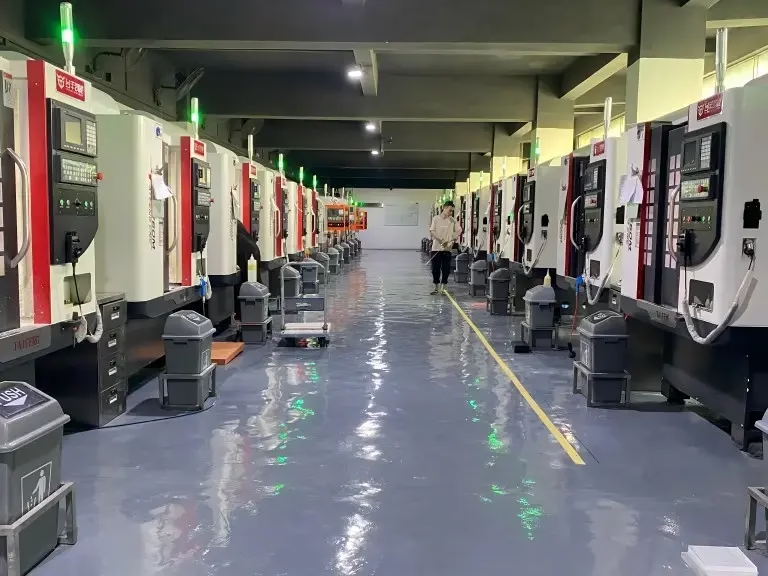
GreatLight runs 16 simultaneous five-axis machining centers alongside 12 four-axis mills, 27 three-axis machines, and 16 mill-turn centers, out of 127 high-precision CNC machines across three wholly-owned plants. Maximum processing size reaches 4,000 mm, with smaller travels of 750 × 1,150 × 550 mm, 600 × 600 × 600 mm, and table sizes down to 500 × 310 × 200 mm for compact work.
Finishing is where the part becomes a medical part. Anodizing, electroless nickel, passivation, bead blasting, and polishing change the surface in ways that affect cleaning, wear, and tissue contact. Laser marking handles UDI and lot traceability, with a minimum character height of 1.5 mm so the mark stays legible after repeated cycles.
The process chain matters as much as the cut. Deburring after milling, cleaning before passivation, and handling between steps all leave marks that a final inspection will find.
- 1Fewer setups, fewer errorsFive-axis access removes re-clamping on multi-face parts.
- 2Match finish to functionRa 0.8–1.6 μm for general surfaces, Ra 0.2–0.8 μm where contact or flow demands it.
- 3Plan the sequenceDeburr and clean before any coating, or the coating traps contamination.
Quality systems and documentation in a regulated supply chain
A medical device manufacturer needs a paper trail, not just good parts. Material certificates, inspection reports, and process records have to survive an audit years after the shipment. That is why the quality system is part of the sourcing decision, not an afterthought.
GreatLight holds ISO 9001:2015, IATF 16949:2016, ISO 13485:2016, and ISO 27001:2022. ISO 13485 covers the medical device quality management requirements. ISO 27001 covers information security, which matters when the deliverable is a CAD file and a drawing pack.
Confidentiality is a practical concern for anyone sending implant geometry or instrument designs. Uploads are handled as secure and confidential, and an NDA is available on request before files change hands.
Documentation should be defined at the quote stage. Say which reports you need, in what format, and whether first-article inspection is required. Agreeing that later costs time and creates gaps.
- 1ISO 13485:2016Medical device quality management system certification.
- 2ISO 27001:2022Information security for design files and correspondence.
- 3Inspection on requestDimensional reports and material certificates available with the shipment.
Machining versus molding for medical parts
Use this when choosing between a machined route and an injection-molded or cast route.
| Factor | CNC machining | Injection molding | Die casting |
|---|---|---|---|
| Tooling cost | None | High, cut before first part | High, plus mold lead time |
| Economic volume | 1 to 10,000+ parts | Roughly 10,000+ parts | Tens of thousands of parts |
| Tolerance | ±0.005 mm achievable | Material and shrink dependent | Wider, post-machining often needed |
| Design changes | Edit the program | Modify or recut the mold | Modify the die |
| Surface finish | Ra 0.2–1.6 μm after finishing | From the mold surface | Usually needs secondary work |
| Best for | Prototypes, instruments, implants | High-volume housings | High-volume structural parts |
| Material range | Metals, plastics, ceramics | Thermoplastics mainly | Non-ferrous metals mainly |
When machining is the right call
If the part is a prototype, an instrument, an implant, or a low-to-mid volume housing, machine it. If it is a simple plastic housing running past 10,000 units a year, mold it and keep machining for the prototype and the first production articles.
Questions engineers ask before sending files
How tight a tolerance can we actually get on a medical part?
GreatLight machines to ±0.005 mm (±0.0002 in) on features that allow it. Whether that holds depends on the feature, the material, and the datum scheme, so list the tight dimensions separately and let the shop confirm each one.
Very small features, deep slots, and thin walls are harder than the blanket number suggests. Expect a conversation about which dimensions carry the function.
What surface finishes are available for implant and instrument surfaces?
As-machined surfaces sit around Ra 1.6–3.2 μm. General functional surfaces typically land at Ra 0.8–1.6 μm, and fine finishing reaches Ra 0.2–0.8 μm.
Finishing options include anodizing, electroless nickel, zinc, silver and gold plating, powder coating, black oxide, bead blasting, tumbling, brushing, and polishing. Laser marking handles traceability with a minimum character height of 1.5 mm.
Is there a minimum order quantity?
No minimum order quantity. Runs go from a single prototype to 10,000+ parts. That is the main reason machining is used early in a program, before mold tooling is justified.
Quotation and a free DFM analysis come back within 12 hours, and production can start within 24 hours of approval.
How are design files protected?
Uploads are secure and confidential, and GreatLight holds ISO 27001:2022 for information security. An NDA is available on request and can be signed before files are sent.
Design files and drawings stay inside the project team.
Which certification matters for medical work?
ISO 13485:2016 is the one that applies to medical device quality management. GreatLight also holds ISO 9001:2015, IATF 16949:2016, and ISO 27001:2022.
Ask for the scope of the certificate, not just the number. It tells you which processes are covered.
How long does a machined medical part take to ship?
Quotation and DFM feedback within 12 hours, production start within 24 hours, and parts ship in 3–5 days. The historical late-delivery probability is below 2%.
Complex geometry or a long finishing chain can extend that. The quote will state the schedule rather than leave it open.
Send a drawing, get a DFM review and a quote
Upload the CAD file and drawing set. We return a quotation and a free DFM analysis within 12 hours, with the tolerance and finishing route stated per feature.
12-hour quote100% inspectionNDA on request
More from GreatLight
We publish setup notes, tooling trials and inspection data from the factory floor.











