
CNC Machining IL: How the Process Works and Where It Stops
A working explanation of CNC machining IL for engineers who buy parts. This page covers how metal is cut, what drives tolerance, and the limits that decide whether a design is machinable at all. Read it and you can tell, before quoting, which features will hold and which will need a change.
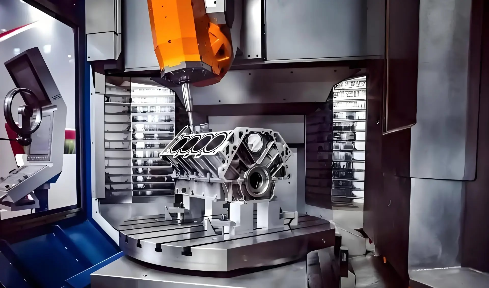
CNC Machining IL: What Happens When a Tool Meets Metal
Shops that do CNC machining IL all run the same loop: a CAM file feeds coordinates to servo drives, the drives move a spindle along linear rails, and a cutting edge shears material away in chips. Nothing about that changes with location. Illinois or Dongguan, the physics is identical. What changes is how well the shop controls the variables around the loop.
The cutting edge does not slice. It pushes until the material fails in shear ahead of the tip. That failure zone is where heat goes, roughly 80% of it into the chip and the rest into the tool and workpiece. If heat stays in the part, the part grows. A 300 mm aluminum plate can move 0.05 mm from a 10 °C rise, which is ten times the tolerance you asked for.
So the first question is never about the machine. It is about chip evacuation and cooling. Aluminum 6061 at 4,000 rpm with proper flood coolant stays dimensionally calm. The same cut with a starved coolant line will rub instead of shear, and the surface tears.
Rigidity is the second variable. A tool hanging 60 mm out of a holder deflects under load. The deflection shows up as taper in a deep pocket and chatter on a thin wall. Shorten the gauge length and the problem usually disappears without touching the program.
- 1Heat follows the chipCoolant and feed rate decide where the temperature ends up.
- 2Deflection beats precisionA rigid setup holds ±0.005 mm; a long tool does not.
Where Tolerance Comes From and Where It Breaks Down
Tolerance is a budget, not a single number. Machine positioning, thermal growth, tool wear, and workholding all draw from the same account. A simultaneous 5-axis machine can position to ±0.005 mm, but that figure assumes the part is held rigidly and the temperature is stable.
Tool wear is the slow leak. A carbide end mill cutting 4140 steel loses edge sharpness over a few hundred millimeters of travel. The diameter you measure at the start of a run is not the diameter at the end. On a 10,000-part order, that drift is the reason in-process checks matter more than the first article.
Workholding is the fast leak. A thin bracket clamped on one edge will lift during the cut. The machinist chases the dimension with offsets and the part still comes out bowed. Adding a support under the cut zone costs a few minutes of setup and saves the whole run.
Surface finish follows the same logic. Ra 0.8–1.6 μm is a normal as-machined result with a sharp tool and a steady feed. Push for Ra 0.2–0.8 μm and you need a finer stepover, a smaller nose radius, or a finishing pass on a separate setup.
- 1In-process monitoringCatch drift before a run goes out of tolerance.
- 2Support under the cutFixturing decides whether the tolerance holds.
The Geometry Limits Nobody Puts on a Drawing
Every cutting tool is a cylinder with a shape on the end. That shape sets the smallest inside corner you can mill. A Ø6 mm end mill leaves a Ø6 mm radius in the corner, no matter what the drawing says. Specify a smaller radius and the shop either uses a smaller tool with more passes, or comes back with a question.
Deep pockets add a second limit. The tool needs length to reach the floor, and length costs rigidity. A pocket 5× deeper than its width is where chatter starts. Below 3× depth-to-width, most materials cut cleanly. Past 5×, expect multiple light passes and a longer cycle.
Fine features have a floor too. Slots narrower than 1 mm, walls thinner than 0.5 mm, and text below 1.5 mm character height all push against what a cutter can do without breaking. Laser marking handles the text case at 1.5 mm minimum height, which is often the better route.
Undercuts and internal channels are the classic hard stop. A 3-axis machine cannot reach them at all. A 5-axis machine with a Ø400 mm rotary table can tilt the part and reach around a feature, but only if there is clearance for the holder. If the holder hits the wall before the cutter reaches the feature, no amount of programming fixes it.
- 1Corner radius ruleInside radius cannot be smaller than the cutter.
- 2Depth-to-width ratioKeep pockets under 3× for a clean cut.
Matching the Machine to the Feature
Pick the machine class from the geometry, not the other way around.
| Feature | Machine class | Typical tolerance | Watch out for |
|---|---|---|---|
| Flat plate, holes on one face | 3-axis | ±0.005 mm | Nothing unusual |
| Part on four sides | 4-axis | ±0.005 mm | Indexing error between faces |
| Angled bore, contoured face | 5-axis simultaneous | ±0.005 mm | Holder clearance at tilt |
| Shaft with turned and milled features | Mill-turn | ±0.005 mm | Feature access from one side |
| Deep pocket, 5× depth | 3-axis, small stepover | ±0.005 mm | Chatter on thin walls |
| Thin wall under 0.5 mm | Any class, light passes | ±0.005 mm | Deflection during clamping |
The Practical Verdict
If the part is a prismatic block with holes on one face, a 3-axis machine is the cheaper and faster answer. If it has angled bores, sculpted surfaces, or features on five faces, pay for 5-axis and get the setup count down.
Questions Engineers Ask Before Quoting
How tight a tolerance can I actually ask for?
±0.005 mm is the working floor for a rigid setup at stable temperature, about ±0.0002 in. Below that, you are buying metrology time as much as machining time. Ask whether the feature is functional or cosmetic first.
If the tolerance is functional, say so on the drawing and let the shop plan the inspection. If it is a habit from an old drawing, loosen it and the price usually drops.
Does the material change the achievable finish?
Yes. Aluminum and brass cut to Ra 0.8–1.6 μm without extra effort. Stainless 316L work-hardens at the cut and needs a sharper edge and a heavier feed to avoid rubbing. Titanium TC4 (Ti-6Al-4V) runs hotter and slower.
For Ra 0.2–0.8 μm, plan a separate finishing pass. Trying to hit it in one pass on stainless usually means a burnt edge and a rejected surface.
What file format should I send?
STEP for solids, because it carries the true geometry. PDF drawings are still useful for tolerances, finishes, and critical features that geometry alone cannot express.
Send both when the part has any callout that is not modeled, such as a press fit or a datum.
When is 5-axis worth the extra cost?
When the part has features on more than three faces, or an angled bore that would otherwise need a custom fixture. One 5-axis setup can replace three 3-axis setups, and each setup you remove removes a stack of positional error.
For a flat bracket with four holes, it is not worth it. For a housing with ports at compound angles, it usually is.
How do you hold thin walls without crushing them?
Support the wall from behind with a soft jaw or a sacrificial block, take light radial passes, and leave the finishing cut for last so the wall still has material around it while the bulk is removed.
Walls under 0.5 mm are possible but the setup dominates the cycle time. Tell the shop up front so it can plan the fixture.
What happens to my drawings and models?
Uploads are kept secure and confidential. An NDA is available on request if your program requires one before files move.
Quote requests get a DFM analysis within 12 hours, which flags the features that will not machine as drawn.
Send the Model, Get the Feedback
Upload a STEP file and get a quotation plus DFM notes within 12 hours. No minimum order quantity, from one prototype to 10,000+ parts.
12-hour quote100% inspectionNDA available
More Process Notes
We publish setup notes, tooling trials and inspection data from the factory floor.











