
CNC machining center work: how the cut actually happens
A practical walkthrough of what goes on inside a machining center, from tool path to chips to the finished part. Written for design engineers and buyers who need to judge whether a feature belongs on a 3-axis, 4-axis or 5-axis setup.
In this article
- 1
- 2
- 3
- 4
- 5
- 6
- 7
What CNC machining center work removes and why it matters
CNC machining center work is subtractive. A rotating cutter removes material from a solid block or casting until the remaining shape matches the CAD model. Nothing is formed or added, so the geometry is only as good as the tool reach and the rigidity of the setup.
The machine reads a program written in G-code. That program lists coordinates, feed rates, spindle speeds and tool changes. The control moves the axes to those coordinates. Positional accuracy of the machine, not the code, sets the floor on what the part can measure.
Two numbers describe most of the result. Tolerance is how close the finished size comes to the nominal dimension. Surface finish is the microscopic texture left by the cutter. A part can hold ±0.005 mm on a bore and still fail if the sealing face sits at Ra 3.2 μm when the drawing calls for Ra 0.8 μm.
Material behavior decides the cutting parameters more than the machine does. Aluminum 6061 cuts fast and throws long chips. 316L stainless work-hardens if the feed is too light. Titanium Ti-6Al-4V needs low surface speed and constant coolant. Inconel punishes any cutter that rubs instead of shears. The same program will not run well across all four.
- 1Subtractive onlyNo material is added, so internal voids and draft angles must exist in the blank.
- 2Program-drivenG-code coordinates drive the axes; the machine's accuracy sets the real limit.
- 3Two key outputsDimensional tolerance and surface finish are measured separately.
- 4Material sets feedsSpeeds and feeds follow the alloy, not the machine model.
Axis count: what each machine can and cannot reach
A 3-axis machine moves the table in X and Y and the spindle in Z. The cutter always approaches along one direction. That is enough for plates, brackets, housings with open faces and any part where every feature is reachable from one of six sides in separate setups.
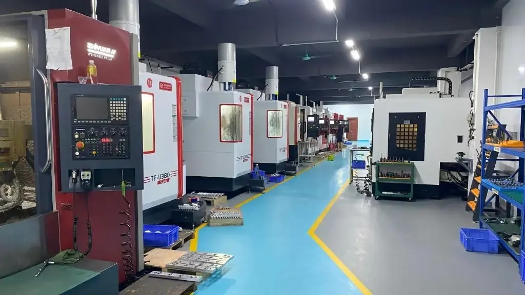
A 4-axis machine adds a rotary table, usually about the X axis. The part turns while the cutter stays in place. This lets you cut a cylindrical pattern of holes or slots in one setup instead of four. On our floor, 12 four-axis mills handle shaft work and parts with repeating features around a bore.
A 5-axis machine adds a second rotary axis, so the tool can tilt relative to the part. Simultaneous 5-axis work lets a ball nose cutter stay normal to a curved surface, which keeps the scallop height even across a contoured face. We run 16 simultaneous 5-axis machining centers.
More axes do not automatically mean better parts. A 5-axis setup costs more per hour, needs more programming time and often needs a longer setup. If a part has three flat faces and a through hole, a 3-axis machine will produce it faster and cheaper with the same tolerance.
- 13-axisFlat faces, open pockets, through holes. Multiple setups for other sides.
- 24-axisShafts, bushings, parts with features repeated around one axis.
- 35-axisContoured surfaces, undercuts, deep cavities reachable only at an angle.
- 4Cost tradeExtra axes add programming and setup time, not just machining time.
Where tolerance and surface finish come from
Tolerance comes from three stacked sources: the machine's positioning error, the deflection of the tool and workpiece under cutting force, and thermal growth during a long run. A rigid setup and a sharp cutter control the middle one. Warm-up and stable coolant control the last one.
We hold ±0.005 mm (±0.0002 in) on critical features. That is not a blanket number for every dimension on every drawing. It applies to features we can probe and measure. A 300 mm long thin wall will move when you release the vise, no matter how good the machine is.
Surface finish follows the cutter geometry and the stepover. A sharp end mill at the right feed leaves Ra 1.6–3.2 μm as-machined. A smaller stepover or a finishing pass with a ball nose gets Ra 0.8–1.6 μm. Polished or lapped faces reach Ra 0.2–0.8 μm.
Finish also depends on the direction of cut. Climb milling usually leaves a cleaner wall than conventional milling on the same material. On stainless and titanium, a dull cutter will smear the surface instead of cutting it, and the finish drops before the dimension does.
- 1Stacked errorMachine positioning, cutting deflection and thermal drift add together.
- 2Probing firstA tolerance claim only holds on features the machine can measure.
- 3Finish by stepoverSmaller stepover and a finishing pass lower the Ra value.
- 4Climb millingCleaner walls on most alloys; smearing signals a worn cutter.
Fixturing, workholding and the limits they set
The fixture decides how much of the part you can reach and how much it distorts. A vise is fast and repeatable for a rectangular blank. Soft jaws machined to the part profile hold better on a finished face. For thin plates, vacuum chucks spread the load and avoid crushing.
Every clamp point leaves a mark or blocks a face. A part that needs all six sides machined must be flipped, which introduces a second datum. Each flip adds error from re-clamping. That is why we try to design the setup so the critical features are cut in one orientation.
Thin walls are the common failure case. A 1 mm wall on a 100 mm aluminum part will deflect under a normal finishing pass. Options are to leave supporting material and remove it later, to reduce the radial depth of cut, or to accept a looser tolerance on that wall.
Residual stress in the blank matters too. A cold-rolled plate or a casting can move after the first cut releases internal stress. Roughing, stress relief and then finishing is the standard answer when a part has to stay flat over a long span.
- 1ViseFast and repeatable for rectangular blanks and simple prismatic parts.
- 2Soft jawsMachined to profile; grips a finished face without denting it.
- 3Vacuum chuckSpreads clamping load on thin plates and large flat panels.
- 4Stress reliefRough, relieve, then finish when flatness matters over long spans.
Material choice changes the whole setup
Aluminum is the default for prototypes and enclosures. Grades 6061 and 7075 cut cleanly at high spindle speeds and take anodizing well. 7075 is stronger but less weldable and more prone to stress cracking in some environments.
Stainless 303 machines easily and is used for fittings and bushings. Grades 304 and 316L are tougher, gummier and work-harden, so the feed must stay heavy enough to cut under the hardened layer. 17-4PH gives high strength after heat treatment and is common in medical and aerospace parts.
Titanium and Inconel are the slow group. Ti-6Al-4V conducts heat poorly, so the cutter edge runs hot. Inconel keeps its strength at temperature and wears tools quickly. Both need lower surface speed, more coolant and a rigid setup. Cycle times are longer and that shows up in the quote.
Plastics behave differently again. POM and PEEK machine well but move with temperature. ABS and PC can melt and smear if the feed is too slow. Carbon fiber composite wears carbide fast and needs dust extraction, which is a separate safety and cleanup requirement.
- 1Aluminum6061, 7075; fast cutting, good for anodizing and prototypes.
- 2Stainless303, 304, 316L, 17-4PH; keep the feed heavy to avoid work hardening.
- 3Titanium and InconelLow surface speed, heavy coolant, longer cycle times.
- 4PlasticsPOM, PEEK, ABS; watch heat buildup and chip clearance.
How the finished part gets checked
Inspection starts before the first cut. We check the raw material certificate against the drawing, so a 7075 part is not made from 6061 stock. Then the first article is measured against the drawing before the run continues.
During the run, the operator checks critical dimensions at set intervals and watches for tool wear. A cutter that has run for hours will change size on a bore. Changing it on schedule is cheaper than scrapping a batch at the end.
Final inspection covers the whole shipment, not a sample. Calipers, micrometers, height gauges and a CMM cover the features that need it. Surface finish is checked with a profilometer when the drawing calls out an Ra value.
Reports are available on request. For regulated work in medical or automotive, the inspection record travels with the parts. The tolerance on paper only means something if there is a measurement behind it.
- 1Material checkCertificate matched to the drawing before cutting starts.
- 2First articleMeasured and signed off before the run continues.
- 3In-processCritical dimensions checked at intervals; tools changed on schedule.
- 4Final100% inspection before shipment; reports on request.
Which setup fits which part
Use this as a first filter before quoting. Part geometry, not the machine list, drives the choice.
| Part feature | 3-axis | 4-axis | 5-axis |
|---|---|---|---|
| Flat plate with open pockets | Best fit | Overkill | Overkill |
| Holes around a bore | Two or more setups | One setup | One setup |
| Shaft with milled flats | Hard to hold | Best fit | Workable |
| Contoured surface | Visible steps | Partial reach | Best fit |
| Deep cavity with undercut | Not reachable | Rarely reachable | Best fit |
| Thin wall, one side open | Workable with support | Workable | Workable with tilt |
| Large frame, 4,000 mm | Best fit on big travels | Limited | Limited |
The short answer
If the part is prismatic and every feature faces one of six directions, use 3-axis and keep the cost down. If features repeat around one axis, use 4-axis and cut them in one setup. Only move to 5-axis when the geometry truly needs a tilted cutter or a single-setup guarantee on a critical datum.
Common questions
How long does it take to get a quote and start cutting?
We return a quotation and a free DFM analysis within 12 hours. Production can start within 24 hours after the drawing and material are confirmed.
Parts ship in 3–5 days for standard work. Complex 5-axis parts or exotic alloys take longer, and we say so in the quote rather than after the order.
Can you make just one part?
Yes. There is no minimum order quantity. We run from a single prototype up to 10,000+ part runs on the same process.
For one-off parts, the setup cost dominates the price. Adding a second or third piece to the same order usually costs much less than a second order later.
What is the largest part you can machine?
Our maximum processing size is 4,000 mm, with large travels of 4,000 × 400 × 150 mm. Medium travels cover 750 × 1,150 × 550 mm and 600 × 600 × 600 mm.
Compact travels of 500 × 500 × 450 mm and 500 × 310 × 200 mm handle smaller parts. A Ø400 mm rotary table supports 4-axis work.
How do you protect my design files?
Uploads are secure and confidential. An NDA is available on request before you send files.
We hold ISO 27001:2022 for information security, alongside ISO 9001:2015, IATF 16949:2016 and ISO 13485:2016 for quality and medical work.
Which materials can you machine?
Aluminum 6061, 7075 and 6082; stainless 303, 304, 316L and 17-4PH; steels 1018, 1045, 4140 and 4340; copper and brass; titanium Ti-6Al-4V; Inconel; magnesium; and plastics including POM, PEEK and ABS.
If a grade is not on the list, ask. We check availability and machinability before quoting instead of substituting a similar grade.
What surface finishes can you deliver?
As-machined surfaces run Ra 1.6–3.2 μm. A finishing pass brings that to Ra 0.8–1.6 μm, and polished or lapped faces reach Ra 0.2–0.8 μm.
We also offer anodizing, plating, powder coating, black oxide, bead blasting and laser marking. Laser-marked characters need a minimum height of 1.5 mm.
Send the drawing, get a real answer
Upload your model and we will come back with a quotation, a DFM note and a recommended setup within 12 hours.
12-hour quote100% inspectionNo minimum order
More from the shop floor
We publish setup notes, tooling trials and inspection data from the factory floor.











