
CNC machining center production design: how a part actually gets made
This page explains what happens between a 3D model and a finished metal part on a CNC machining center. It is written for design engineers and buyers who need to judge whether a feature is machinable, what tolerance is realistic, and when a machining center is the wrong process.
In this article
- 1
- 2
- 3
- 4
- 5
- 6
- 7
What a CNC machining center is doing mechanically
A CNC machining center is a machine tool that holds a rotating cutting tool and moves it through a programmed path while the workpiece sits clamped on a table or fixture. The controller reads G-code, closes the position loop with servo feedback, and drives the axes to follow that path. Milling, drilling, tapping, boring and helical interpolation are all the same motion in different shapes.
The word center matters. A machining center carries a tool magazine, so it changes tools automatically instead of an operator swapping cutters. That is what turns a single-purpose mill into a production machine: one setup can drill, rough, semi-finish, finish and tap without the part ever leaving the fixture.
Everything downstream in production design follows from that. Because the part stays clamped, you can hold position between features. Because tool changes are automatic, cycle time is dominated by cutting time, not handling time. And because the machine is rigid and thermally controlled, the achievable tolerance is a machine property, not an operator skill.
3-axis, 4-axis and 5-axis: what each one buys you
A 3-axis machining center moves X, Y and Z only. The tool always approaches from one direction. This is the cheapest and fastest way to make a part whose features all face the same way: plates, housings with one open face, brackets, manifolds from one side. Most production parts never need more.
A 4-axis machine adds a rotary table, usually turning about X or Y. That lets the part index to a new face without a second setup. Holes on four sides, cross-drilled shafts, and parts with features at 90 degrees to each other become one-op jobs. Position between faces is set by the rotary encoder, not by re-clamping.
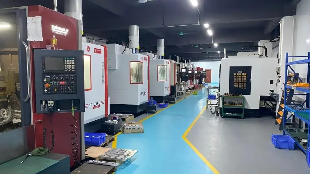
A 5-axis machine adds a second rotary axis, so the tool can tilt relative to the part. Two things become possible. First, undercut and contoured surfaces can be cut in one continuous pass instead of many 3-axis passes. Second, short stub tools can reach deep pockets because the machine tilts the part toward the cutter instead of burying a long tool. GreatLight runs 16 simultaneous 5-axis centers alongside 12 four-axis mills and 27 three-axis machines, so the axis count is chosen per part rather than by what is available.
- 1Pick 3-axisAll features are reachable from one direction and the part is prismatic.
- 2Pick 4-axisFeatures repeat around an axis or on several indexed faces.
- 3Pick 5-axisContoured surfaces, deep pockets, or features at compound angles.
Workholding and datum design decide whether the tolerance holds
The cutting tool is only half the accuracy problem. The other half is how the part is held. A vise clamped on a raw sawn face gives you a datum that varies from part to part. A fixture located off two bored holes and a machined face gives you a datum that repeats within a few microns. Production design means choosing the second.
For anything past a handful of parts we build a soft-jaw or dedicated fixture and machine the locating surfaces on the machine itself. That ties the fixture datum to the spindle, which removes stack-up from the setup. Thin walls, rings and long shafts get support from the fixture, not from extra clamping force, because clamping force is what deforms a part and springs it back after unclamping.
The practical rule: identify which surfaces the drawing calls out as datums, and make sure those surfaces exist in the raw stock or are cut in the first operation. If a critical dimension is measured from a face that gets machined in op two, the tolerance chain just got longer for no reason.
Tool path design, chip evacuation and thermal behavior
Cam software will generate a path for almost anything. The question is whether the path can be cut at a sensible feed rate without chatter, tool wear or heat buildup. Deep pockets with a small corner radius force a small-diameter tool on a long reach. That tool deflects, so the surface finish drops and the wall may taper. Opening the corner radius to at least one third of the pocket depth usually removes the problem.
Chip evacuation is the quiet constraint. Aluminium at 6061 or 7075 cuts fast and produces a large chip volume; if chips recut, the finish scuffs and the tool edge chips. Through-spindle coolant or high-pressure flood solves it. Titanium and Inconel behave the opposite way: they conduct heat poorly, so the heat goes into the tool edge. Lower surface speed, heavier feed per tooth and a lot of coolant keep the edge alive.
Thermal drift is real on long cycles. A machine that has been running for six hours is not the same size as one that started cold. For tight work we let the machine warm up, keep the coolant at a controlled temperature, and take finishing passes after roughing has stabilized the part. That is how ±0.005 mm stays repeatable instead of becoming a one-off measurement.
Material behavior changes the production design
Aluminium alloys 6061-T6, 7075 and 6082 machine cleanly and hold tight tolerances, which is why they dominate prototype and production machining. 7075 gives higher strength but is more notch-sensitive and galls more easily, so tool geometry and coolant matter more. Magnesium AZ31B and AZ91D cut very fast but the chips are flammable; that is a housekeeping and coolant discipline problem, not a machining problem.
Stainless 303 and 304 work-harden if the tool rubs instead of cutting, so the feed per tooth has to stay above a floor. 17-4PH in the H900 condition is strong and dimensionally stable after machining, which suits aerospace and medical hardware. Titanium Ti-6Al-4V and Inconel are where production design pays off most: roughing strategy, tool path engagement and rigidity control decide whether the part takes forty minutes or four hours.
Plastics behave differently again. POM and PEEK hold tolerance well but move with temperature; ABS and PC are soft and easy to mark. The design implication is simple: on plastics, plan the finishing pass to remove very little material, and expect clamping marks unless the fixture is shaped to the part.
When a CNC machining center is the wrong choice
Machining removes material, so cost scales with the volume you cut away. A part that starts as a 6 kg block and finishes at 400 g wastes most of the cycle time making chips. If the geometry is a shell or a housing with thin uniform walls, die casting or vacuum casting produces the near-net shape first, and machining becomes a finishing operation on the critical faces only.
Thin, flat, large panels are another boundary. A 1 mm aluminium cover 500 mm across will deflect under its own cutting forces no matter how good the fixture is. Sheet metal fabrication wins there. Likewise, anything with internal channels that no tool can reach, or with a lattice interior, is a candidate for 3D printing rather than machining.
The honest split is this: machining is unbeatable for tight tolerance, good surface finish, strong material properties and moderate complexity. It is the wrong tool for hollow, thin-walled, high-volume parts where the geometry is mostly empty space.
- 1Stay with machiningTight tolerance, dense features, structural load paths, small to mid volume.
- 2Switch to castingThin uniform walls, mostly hollow geometry, higher annual volume.
- 3Switch to sheet metalFlat panels, bends, large thin covers.
Choosing the machine and process for a part
Match the part geometry to the machine configuration before quoting.
| Part characteristic | Machine / process | Why | Watch out for |
|---|---|---|---|
| One open face, prismatic | 3-axis vertical | Fastest cycle, simple fixture | Second op for back-side features |
| Features on 4 sides | 4-axis with rotary table | One setup, indexed positions | Rotary table swing clearance |
| Compound angles, deep pockets | 5-axis simultaneous | Short tools, contoured passes | Programming and cycle cost |
| Shaft with milled flats | Mill-turn center | Turning and milling in one op | Bar diameter limits |
| Thin uniform shell | Die casting plus finish | Near-net shape saves material | Porosity and draft angles |
| Flat panel under 2 mm | Sheet metal fabrication | No cutting-force deflection | Bend radius and tolerance stack |
| Internal lattice or channels | 3D printing | Tool cannot reach inside | Surface finish and strength |
The short version
If your part is dense, needs tight tolerance and carries load, design it for a CNC machining center and spend your effort on datums, corner radii and wall thickness. If your part is mostly empty space, thin-walled or needed in high volume, machine only the critical faces and form the rest with casting, sheet metal or printing.
Questions engineers ask before releasing a design
What tolerance can a CNC machining center actually hold in production?
On a rigid setup with a controlled process, ±0.005 mm (±0.0002 in) is achievable on critical features such as bores and locating faces. That figure applies to the feature, not to every dimension on the drawing.
General dimensions on the same part can sit at ±0.05 mm and cut cost. Tighten only the features that need it.
What surface finish should I specify?
As-machined is Ra 1.6–3.2 μm. A normal finishing pass reaches Ra 0.8–1.6 μm. Fine finishing reaches Ra 0.2–0.8 μm and needs a separate light pass with a sharp tool and a stable setup.
Specifying Ra 0.4 μm on a deep pocket is usually wasted. Specify it on sealing faces, bearing bores and sliding surfaces.
How deep can a pocket be cut?
A common working limit is four times the tool diameter for a rigid carbide end mill in aluminium, less in stainless and titanium. Beyond that, tool deflection starts to show as taper and chatter.
If the design needs more, plan a corner radius of at least one third of the pocket depth so a larger tool can be used.
How thin can a machined wall be?
In aluminium, 0.8 mm walls are practical with light finishing passes and a supporting fixture. In stainless and titanium, 1.5 mm is a safer floor. Below that, the wall deflects during cutting and springs back after unclamping.
Add a small fillet at the wall base. It raises stiffness without adding weight.
Do I need a drawing, or is a 3D model enough?
A 3D model plus a 2D drawing that marks datums, critical dimensions and tolerances is the cleanest input. The model defines the shape; the drawing defines what is inspected.
If only a model is available, we will flag the dimensions that need a tolerance call before production starts.
How is confidentiality handled?
Uploads are secure and confidential, and an NDA is available on request. Production files are kept under access control and only reach the engineers and machinists working on the job.
Send the model, get a DFM review back
We review your design for machinability, datums and tolerance stack, then quote it. Quotation and free DFM analysis within 12 hours.
12-hour quote±0.005 mm100% inspectionNo MOQ
More from the shop floor
We publish setup notes, tooling trials and inspection data from the factory floor.











