
Case: 3D Scanning Helps Large Steam Turbine Castings Detect Margins and Mark Lines
Large castings arrive with tolerance stack-ups that no drawing can capture. We scan them before machining, compare the point cloud to the CAD model, and mark the real stock condition on the part. This page is for engineers and buyers who need to know what scanning can and cannot decide on a 2-tonne turbine housing.
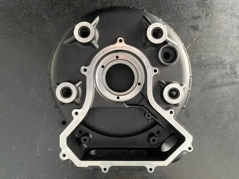
Why a 3D scan comes before the first cut
A casting that is 6 mm off nominal will not clean up, and no setup sheet tells you which face to trust until you measure the whole part.
What goes wrong when a large casting reaches the machine
A steam turbine casing is a sand casting, usually 1 to 6 tonnes and 1,500 to 4,000 mm across. Draft angles, core shift, and uneven cooling mean the as-cast surface never sits exactly where the model says. The split faces, the bore, and the flange bolt circle are the areas that carry the tightest requirements, often ±0.1 mm or better after final boring.
The machine shop gets a part with no reliable reference. Clamp it on the raw surface and the first face may cut clean while the opposite flange runs 4 mm short of stock. Move the setup to chase that flange and the bore loses its wall thickness. Scrap risk on a part this size is not a rework cost, it is a remelt and a lost month.
Traditional layout uses height gauges, scribes, and a surface plate. That works on a 200 mm bracket. On a 3,000 mm casting the plate does not exist, the operator cannot reach the middle of a curved wall, and every measurement is relative to an edge that is itself out of tolerance.
This is where the case for 3D scanning helps most. Before any metal is cut, the shop needs a map of the actual stock: how much material sits on every machined face, where the walls are thin, and which datum set makes the whole part clean up.
Scanning a 2-tonne casting on the shop floor
We use a handheld or tripod-mounted structured-light scanner with photogrammetry targets for the large volume. The part is placed on a stable stand, not a granite plate. Reference targets are stuck to the casting and to the floor around it, then a photogrammetry pass locks the global coordinate frame to within about 0.1 mm over a 4 m diagonal.
The scan itself captures the whole exterior: split faces, flanges, nozzle openings, ribs, and the rough as-cast skin. Interior bores and deep cavities are captured separately with a smaller scanner head or a bore gauge, then merged. Total capture time on a 3 m casing runs 2 to 4 hours, depending on surface finish. Painted or heavily rusted surfaces need a matte spray first.
Registration is the step that decides everything. The point cloud is aligned to the CAD model using the datum scheme the drawing calls for, not a best-fit over the whole part. A global best-fit will average every error and hide the one face that matters. We run several alignment trials and compare the resulting stock maps before choosing.
The output is a color map in 0.5 mm bands. Blue means no stock, green means roughly 1 to 2 mm, yellow 2 to 4 mm, red above that. On a turbine casing the useful question is not the average deviation. It is the minimum stock on each machined face, and whether the minimum is positive everywhere.
- 1Targets before scanningPhotogrammetry frames the whole part; without it, long scans drift.
- 2Matte spray for shiny castingsBare or machined surfaces reflect; uncoated scans show holes.
- 3Separate bore captureDeep ID features need a second pass and a merge check.
- 4Datum-led alignmentBest-fit over the whole part hides the critical face.
When 3D scanning pays off, and when it does not
Not every casting needs a full scan. Use this as a first filter before booking inspection time.
| Part condition | Scan useful? | What it decides |
|---|---|---|
| First article, new pattern | Yes, always | Whether the pattern needs correction before a full run |
| Large casting, tight wall | Yes | Thinnest wall location and minimum stock per face |
| Repeated production, stable pattern | Spot checks only | Drift over batches, not every part |
| Simple plate or bar stock | No | Stock is known; a caliper and a height gauge are enough |
| Fully machined part | Usually no | CMM probing on the finished datum is faster and tighter |
| Damaged or welded casting | Yes, if re-machining | Which faces still have stock after repair |
Turning a point cloud into lines on the casting
A color map on a screen does not help the operator standing at a 3 m boring mill. The scan has to come back to the part as physical marks. We project the machining lines, the split-face centerline, and the bolt circle onto the casting using a laser projector aligned to the same coordinate frame as the scan.
The projector throws the CAD curves directly onto the rough surface at 1:1. The operator scribes or punches along the projected line, then the projector is removed and the setup proceeds normally. Position accuracy on the surface is roughly ±0.3 mm over the projected area, which is enough to place a roughing allowance but not enough to substitute for a bored datum.
For smaller castings that will not fit under a projector, or when the shop wants a permanent record, we mark with a CNC layout machine or a portable arm. The arm probes the surface at the scan-derived coordinates and scribes the same lines. Slower, but it works on a part that is already clamped in the machine.
The marks are not the final dimension. They tell the operator where the nominal feature sits relative to the real casting. After the first face is cut, the machined surface becomes the datum and all subsequent work references it, not the scan.
What the scan cannot tell you
Scanning measures the outside of the part. Internal porosity, shrinkage voids, and core-related defects sit inside the wall and will not show up on a surface deviation map. A wall that reads 12 mm on the scan may still have a gas pocket at 6 mm depth. For critical pressure boundaries, ultrasonic testing or radiography is the right tool, not scanning.
The scan also has no opinion on material condition. Stress relief state, hardness, and residual stress after welding are outside its scope. If the part will be machined, welded, and machined again, the scan only describes the geometry at the moment of capture.
Surface finish limits accuracy. A rough sand-cast skin scatters the light and adds noise, typically 0.1 to 0.3 mm on as-cast surfaces. Machined or blasted surfaces scan tighter, often under 0.1 mm. When the decision hinges on a 0.2 mm margin, we scan the machined faces rather than the raw skin.
Finally, a scan is a snapshot of one part. It does not tell you whether the next casting from the same pattern will behave the same way. Pattern wear, sand condition, and pour temperature all move the result. That is why we recommend scanning the first article, then sampling at a defined interval rather than scanning every piece.
Questions engineers ask before booking a scan
How accurate is a 3D scan on a large rough casting?
On as-cast sand surfaces, expect 0.1 to 0.3 mm of noise from the skin alone, on top of the scanner's own accuracy. Photogrammetry keeps global drift to about 0.1 mm over a 4 m diagonal.
On machined or blasted faces the noise drops and the useful resolution is under 0.1 mm. We scan the faces that carry the decision, not the whole part at one setting.
Can a scan replace a CMM inspection report?
No. A scan is a fast, dense surface comparison against CAD. A CMM is a calibrated, traceable measurement of specific features using a defined datum.
Use the scan to decide stock and setup. Use the CMM to certify the finished dimensions against the drawing. The two answer different questions.
How long does the scan and marking take on a 3 m casing?
Capture runs 2 to 4 hours depending on surface condition and how many internal features need a second pass. Alignment and stock mapping add another 1 to 2 hours.
Laser projection and marking on the part take roughly 1 hour per setup. Total is usually one working day before the first cut.
What do you need from us to run the scan?
The 3D CAD model with the datum scheme called out, plus the drawing that defines which faces are machined and to what tolerance. A step or parasolid file is fine.
Tell us the critical faces and the minimum wall requirement. Without that, the alignment cannot be optimized for the features that matter.
Does scanning add cost to the part?
It adds inspection hours before machining. On a large casting that is small next to the cost of a scrapped part or a re-weld.
On a stable, repeated production run we drop to sampling, so the per-part cost falls after the first article is proven.
Can you scan a casting that is already on the machine?
Yes, if the scanner can reach the surfaces and targets can be placed without disturbing the setup. A portable arm works better in that case than a tripod scanner.
The alignment then references the machine coordinate frame, so the marks line up with the current setup rather than the drawing datum.
Have a casting that needs a stock check before setup?
Send the CAD model and the drawing. We will confirm the scan scope, the datum scheme, and whether the part is a candidate for scan-and-mark.
12-hour quote and DFM±0.005 mm machining tolerance100% inspection before shipmentNDA on request









