
C TEK CNC Machining Technology: How Multi-Axis Cutting Actually Works
This page explains what C TEK CNC machining technology does inside the machine: how axes move, how the part is held, how heat and tool wear shift dimensions, and where the process stops being economic. It is written for design and process engineers who need to judge whether a geometry belongs on a mill-turn center or somewhere else.
In this article
- 1
- 2
- 3
- 4
- 5
- 6
- 7
What C TEK CNC Machining Technology Changes on the Shop Floor
C TEK CNC machining technology is the practice of cutting a metal or plastic part by moving a rotating tool along controlled axes while the workpiece stays clamped. The control reads a toolpath, corrects for tool radius and length, and drives ball screws to follow that path. Everything downstream, tolerance, finish, cycle time, comes from how well the machine holds that path under load.
The difference between a three-axis mill and a five-axis center is not speed. It is how many setups a part needs. On a three-axis machine, a part with features on five faces is repositioned several times. Each reposition adds a datum shift. A simultaneous five-axis center reaches those faces in one setup, so the same datum carries through the whole part.
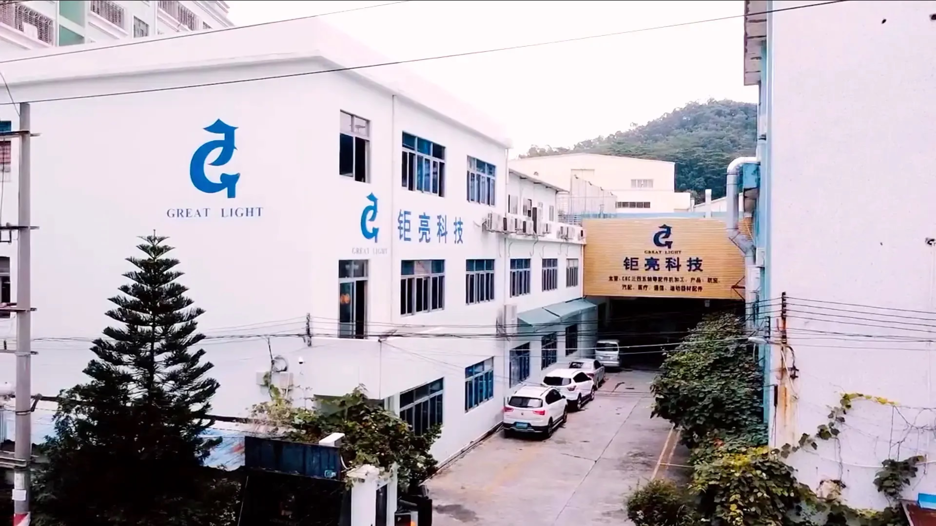
GreatLight runs 127 high-precision CNC machines, including 16 simultaneous five-axis machining centers, 12 four-axis mills, 27 three-axis machines and 16 mill-turn centers. The largest travel is 4,000 × 400 × 150 mm; a Ø400 mm rotary table handles round work. That mix matters more than a single headline machine.
- 1One setup, one datumFewer re-clamps means less stacked error between features.
- 2Tool access, not just reachTilting the table keeps a short, stiff tool in the cut.
- 3Chip evacuationGravity helps when the part can be oriented for the cut.
Axes, Kinematics and Why Tool Length Changes Everything
A five-axis machine adds two rotary axes to the three linear ones. The common trunnion layout puts a C-axis table on top of an A-axis cradle, so the part rotates under the spindle. The alternative is a swivel head, where the spindle tilts instead. Trunnion machines handle heavier parts and are easier to probe; swivel-head machines reach into deep pockets on large frames.
Kinematics decide what the tool can actually do. A short tool with a large diameter resists deflection; a long tool reaches but bends. Deflection shows up as chatter, then as a dimension that drifts across the batch. When a feature sits 200 mm deep in a pocket, the tool needed to reach it may be long enough that cutting forces push it off path.
This is where programming discipline pays off. Roughing with a stubby tool and finishing with a long one, tilting the part so the finishing tool stays short, and leaving 0.3–0.5 mm of stock for the finish pass all reduce the problem. If none of those work, the geometry has to change.
- 1Rough with short toolsRemove most stock before the long tool enters the cut.
- 2Tilt for stiffnessOrient the part so the finishing tool is as short as possible.
- 3Watch the L/D ratioTool length over diameter above 6:1 invites chatter.
Workholding: Where Most Tolerance Loss Happens
A machine can hold ±0.005 mm and still produce a part that is out of tolerance, because the part moves when it is released. Thin walls, long slender parts and anything machined from plate carry residual stress. Cut one side, flip it, cut the other, and the part bows. The dimension was correct while clamped and wrong after unclamping.
The fixes are mechanical, not software. Stress-relieve plate before the first cut. Machine equal amounts from both sides of a thin wall. Leave a sacrificial web or tabs so the part stays connected until the last operation. For a 1.5 mm wall in aluminium, a light finishing pass at 0.1–0.2 mm radial engagement cuts load and heat at the same time.
Fixtures matter too. Soft jaws machined to the actual part profile grip better than a vise with three contact points. For a run of 10,000 parts, a dedicated fixture pays for itself in scrap avoided. For a single prototype, a machined pocket in a scrap block is enough. Match the fixture to the batch, not to the drawing.
- 1Relieve before machiningStress in rolled plate will move the part after cutting.
- 2Balance the cutsEqual stock removal from both faces keeps the wall straight.
- 3Keep tabs until lastTabs stop thin sections from ringing during finishing.
Heat, Tool Wear and the Slow Drift of a Long Run
Cutting generates heat in three places: the shear zone where the chip forms, the rake face of the insert, and the flank rubbing the finished surface. Most of it leaves with the chip. What stays in the part raises its temperature, and the part grows. Aluminium expands about 23 μm per metre per degree Celsius. A 100 mm aluminium bore that is 10 °C warmer than the inspection room is roughly 23 μm larger. That is more than four times the tolerance band.
This is why parts are measured at 20 °C, and why a hot part measured on the machine reads differently from the same part on a granite plate an hour later. In-process probing catches the trend only if the part has cooled, or if the probe data is compensated.
Tool wear is the second drift. A carbide insert that has cut 200 aluminium parts has a worn nose radius. The surface finish creeps from Ra 0.8 μm toward Ra 1.6 μm, and the effective diameter shifts. Indexing on a fixed schedule, rather than waiting for a bad part, keeps the batch inside tolerance.
- 1Measure at 20 °CLet the part stabilize before final inspection.
- 2Index on scheduleChange inserts by part count, not by sound.
- 3Watch roughing heatHeavy passes leave heat the finishing tool cannot remove.
How Material Choice Rewrites the Cutting Parameters
Aluminium 6061-T6 machines fast. Surface speed of 300–500 m/min is normal, and the material clears chips well. It also moves after machining because it is heat-treated and lightly stressed. Grade 7075 cuts cleanly and holds a better finish, but it is less corrosion-resistant without anodizing. For a housing that is mostly cosmetic, 6061 is fine. For a bracket carrying load, 7075 or 6082 holds shape better.
Stainless 304 work-hardens. If the tool rubs instead of cutting, the surface gets harder and the next pass is worse. The answer is a positive-rake insert, a feed rate high enough to stay under the hardened layer, and no dwelling. Grade 316L behaves the same way and is the usual choice for medical parts that need corrosion resistance.
Titanium Ti-6Al-4V and Inconel 718 sit at the other end. They conduct heat poorly, so the cutting edge absorbs it. Speeds drop to 30–60 m/min for titanium and lower for Inconel. Tool life becomes the constraint, and the process may need high-pressure coolant or a ceramic insert to stay economic. Finishes run from Ra 1.6–3.2 μm as-machined to Ra 0.2–0.8 μm after fine finishing.
- 1Aluminium is forgivingFast speeds, good chip clearance, watch residual stress.
- 2Stainless work-hardensKeep the tool cutting; never let it rub.
- 3Titanium holds heatLower speeds, more coolant, shorter tool life.
Inspection: Turning Machine Capability into Shipped Conformance
A tolerance on a drawing is a claim about the whole batch, not one part. To support that claim, the process needs a measurement loop. GreatLight checks raw material on receipt, monitors dimensions during the run, and inspects 100% of parts before shipment, with reports on request. The point of the in-process step is to catch drift while there is still stock to correct it.
Coordinate measuring machines handle position and form: true position of a hole pattern, flatness of a sealing face, perpendicularity of a bore to a mounting plane. A granite surface plate and height gauge still work well for a single critical dimension on a simple part, and they are faster.
Some features cannot be verified after the fact. A cross-drilled oil passage that breaks into another bore can only be confirmed with a borescope or a flow test. If the drawing calls out a flow rate, plan that test into the process, not into the final inspection queue. Capability is proven before the run, not after.
- 1In-process beats finalCatch drift while there is still stock to cut.
- 2Match the gauge to the featureCMM for position and form, plate for a single dimension.
- 3Plan hidden features earlyInternal passages may need flow or vision checks.
Which Machine Class Fits Your Part
Pick the class by feature count, tolerance and batch size, not by machine age.
| Machine class | Typical part | Holds well | Watch out for |
|---|---|---|---|
| 3-axis mill | Flat plates, open pockets, one-face work | ±0.01 mm on simple features | Extra setups on multi-face parts |
| 4-axis mill | Shafts, cylinders with cross features | ±0.01 mm around the axis | Only one rotary axis of access |
| Simultaneous 5-axis | Impellers, contoured housings, deep pockets | ±0.005 mm in one setup | Programming and fixture cost |
| Mill-turn | Round parts with milled flats | ±0.005 mm across both operations | Long slender parts deflect |
| Large-travel mill | Frames up to 4,000 mm | ±0.01 mm over long spans | Thermal growth over long cycles |
When Multi-Axis Is Worth It, and When It Is Not
If the part has features on four or more faces, a contoured surface, or a tolerance tighter than ±0.01 mm that spans two datums, run it on a simultaneous five-axis center. If it is a flat plate with holes, a three-axis mill in soft jaws will hit the same numbers for less money.
Questions Engineers Ask
Can C TEK CNC machining technology hold ±0.005 mm on every feature?
No. That figure is the tight end of what the process can reach under good conditions: a rigid setup, a short tool, a stable material and a temperature-controlled environment. Features far from the datum, deep pockets and thin walls all widen the real spread.
When a drawing calls for ±0.005 mm, we look at where that tolerance sits. Two mating bores 50 mm apart are achievable. The same tolerance on a 1 mm wall 400 mm from the fixture is a different problem, and it may need a process change or a design change.
Which materials are a poor fit for multi-axis milling?
Very soft, gummy plastics such as LDPE and unfilled PP are hard to cut cleanly; they smear instead of forming chips. They are usually better on a router or as a molded part.
Hardened tool steel above 45 HRC also pushes conventional milling past its limit. That is EDM or grinding work, or it needs an annealed blank that is hardened after machining.
Does one setup really remove more error than three setups?
Yes, because each setup introduces a new datum. The part is unclamped, moved, re-clamped and re-zeroed, and every one of those steps adds a small offset that stacks with the others.
On a part with six faces of features, three setups can add 20–40 μm of position error before any cutting error is counted. One setup removes that stack entirely, which is often worth more than the machine's nominal accuracy.
How do you handle parts that move after machining?
We stress-relieve the blank first when the material allows it. We balance stock removal between opposite faces. We leave tabs or a sacrificial web so the part keeps its shape until the last operation.
For very thin sections, we may take a light finishing pass at 0.1–0.2 mm radial engagement to limit cutting load. If the part still moves, the next step is a design change, not a longer cycle.
What surface finishes are realistic without extra processing?
As-machined finish lands around Ra 1.6–3.2 μm on most metals with a standard finishing pass. A fine finishing strategy with a smaller stepover reaches Ra 0.8–1.6 μm.
Ra 0.2–0.8 μm is achievable on aluminium and some steels, but it takes a dedicated finishing pass, a fresh tool and more time. If the drawing only needs a sealing surface, Ra 1.6 μm is usually enough.
How does the quote and DFM step work?
Upload the model and drawing and we return a quotation with a free DFM analysis within 12 hours. The analysis flags features that will be hard to hold, thin walls, deep pockets, tight corners, and suggests changes.
Production can start within 24 hours of approval, and parts typically ship in 3–5 days. There is no minimum order quantity, so a single prototype and a 10,000-part run go through the same review. Uploads stay confidential and an NDA is available on request.
Send the Drawing, Get a Process Answer
Upload your model and we will return a quote with a free DFM analysis within 12 hours, plus a straight answer on which machine class the part belongs on.
12-hour quote100% inspectionNo minimum order quantity
More From the Shop Floor
We publish setup notes, tooling trials and inspection data from the factory floor.











