
Basic Knowledge of Aluminum CNC Milling
This page covers the working knowledge an engineer needs before quoting or designing an aluminum milled part: which alloy to pick, how the cut behaves, where the part will move, and what the finish really costs. It is written for design engineers and buyers who read drawings. After it you can judge whether a part belongs on a 3-axis or a 5-axis machine, and which questions to ask before release.
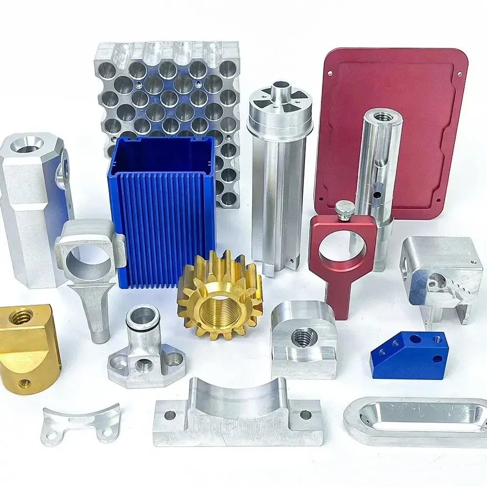
What this guide covers
Aluminum is the default metal for milled prototypes and small production runs. The reasons are mechanical, not marketing.
Why aluminum mills so well, and where it fights back
Aluminum cuts at high surface speed. A carbide end mill in 6061 can run 3 to 5 times faster than the same tool in 4140 steel, and the cutting force is roughly a third. That means lighter fixtures, thinner walls, and faster cycle time. Thermal conductivity is about 200 W/m·K for 6061, so heat leaves with the chip instead of soaking into the part. On a well-run job the part stays close to room temperature.
The trade-off is stiffness. Aluminum has a Young's modulus near 69 GPa, about one third of steel. A 1.5 mm wall will deflect under clamping and under cutting load even when the toolpath is correct. Deep pockets and tall thin ribs need support or light finishing passes. If you design a 0.8 mm floor on a 100 mm pocket, no machine setting will save the tolerance.
Built-up edge is the other common problem. Soft alloys such as 5052 and 6063 tend to weld onto the cutting edge when speed is too low or the tool has too little rake. The symptom is a rough, smeared surface and a sudden change in dimension. Sharp, polished flutes and 8 to 12 percent cobalt in the carbide help. So does never letting the tool rub: keep the feed per tooth up and the radial engagement down.
- 1Good fitBrackets, housings, heat sinks, manifolds, fixture plates, robot arms
- 2Watch closelyThin floors, tall ribs, long unsupported bores, tight flatness over 300 mm
- 3Poor fitParts needing high wear resistance or continuous service above 200 °C
Common aluminum alloys for CNC milling
Pick by function first, then by finish and availability.
| Alloy | Typical use | Machinability | Notes |
|---|---|---|---|
| 6061-T6 | General parts, fixtures, housings | Excellent | Weldable, anodizes evenly |
| 7075-T6 | High-strength structural parts | Good | Strong, less corrosion resistant |
| 2024-T4 | Aircraft structure, fatigue parts | Fair | Poor corrosion resistance bare |
| 5052 | Sheet and formed panels | Fair | Tough, gummy at low speed |
| 6082-T6 | European structural parts | Very good | Close to 6061 in behavior |
| ADC12 | Die-cast housings, post-machined | Good | Cast porosity can open up |
How a milling job is actually run
Milling removes material with a rotating multi-flute cutter while the part or the tool moves along controlled axes. For aluminum, a 3-flute carbide end mill is the workhorse: it leaves enough room for the chip to clear in the soft material. Two-flute tools suit slotting and plunging. Four or more flutes suit finishing passes where chip load per tooth is small.
The sequence on a typical part starts with facing the stock, then roughing, then semi-finishing, then finishing. Roughing removes 70 to 90 percent of the volume with a large axial depth and small radial width. This keeps the tool engaged on its side rather than its tip, spreads wear, and limits heat. Finishing takes 0.2 to 0.5 mm on walls and floors to hold the final dimension and surface finish.
Climb milling is standard on CNC machines. The cutter tooth enters at maximum chip thickness and exits at zero, which pushes the part away from the tool and gives a cleaner wall. Conventional milling is still used for rough cast surfaces or when the machine has backlash. For a 6 mm 3-flute tool in 6061, a starting point is 12,000 rpm, 1,800 mm/min feed, 6 mm axial depth, and 1.8 mm radial width. Adjust from the chip shape and the sound, not from a chart alone.
- 1RoughingLarge axial, small radial, high feed per tooth
- 2FinishingSmall step-over, sharp tool, steady coolant or air blast
- 3CoolantMist or air often beats flood on aluminum; chips clear better
Holding tolerance and controlling distortion
A tolerance of ±0.005 mm is achievable on aluminum when the part is rigid, the machine is thermally stable, and the inspection method matches the drawing. It is not achievable on a 300 mm thin plate with no fixturing plan. Distortion comes from three places: residual stress in the stock, heat from cutting, and clamping force. Stress-relieved plate costs more but removes the first source.
Workholding decides the result more often than the spindle does. A vise on a 2 mm wall will bend the wall before the first cut. Vacuum plates, soft jaws machined to the part profile, and low-melt fixturing all spread the load. For thin floors, support underneath with a sacrificial block and leave tabs until the last operation. Then remove tabs in a separate light pass.
Measure with the part free, not clamped. A bore that reads Ø20.000 mm in the vise can spring to Ø19.985 mm after release. Temperature matters too: a 100 mm aluminum part grows about 0.0023 mm per 1 °C, so a cold morning inspection and a warm afternoon inspection will disagree. Let the part sit and stabilize before final measurement.
When 5-axis earns its place
Three-axis milling handles the majority of aluminum parts: plates, brackets, simple housings with open faces. The setup is simple and the cost is low. Four-axis adds rotation around one axis, which suits parts with features on multiple sides around a cylinder, such as a manifold or a shaft with milled flats.
Five-axis becomes the cheaper option once a part needs work on four or more faces, or when the geometry has compound angles and curved surfaces that would otherwise need three or four separate fixtures. Each re-fixture adds setup time, and each re-clamp adds a chance to lose position. A simultaneous 5-axis center can reach undercuts and drill angled holes in one pass, which also improves surface quality on contoured surfaces because the tool stays normal to the surface.
The limit is not the machine but the reach and the rigidity at the end of it. Deep cavities in a large part may still need a long tool, and a long tool deflects. For those cases we often rough on a 3-axis machine and finish the critical faces on 5-axis, which keeps the tool short. GreatLight runs 16 simultaneous 5-axis machining centers and 27 three-axis machines, so the routing follows the part rather than the other way around.
- 13-axisFlat plates, open pockets, single-face work
- 24-axisCylindrical parts with side features
- 35-axisCompound angles, deep undercuts, contoured surfaces
Surface finish and post-processing
As-machined aluminum from a sharp cutter lands around Ra 1.6–3.2 μm. A finishing pass with a smaller step-over and a fresh tool can reach Ra 0.8–1.6 μm. Below that, Ra 0.2–0.8 μm, requires either a fine finishing strategy or a secondary operation such as polishing. Each step adds time, so decide early whether the drawing needs a number or just a look.
Anodizing is the most common aluminum finish. Clear anodizing preserves the metal look, color anodizing adds dye, and hardcoat builds a thicker oxide for wear resistance. Type II clear is the default for cosmetic parts. Hardcoat changes the dimension by roughly half the coating thickness per surface, so bores and threads that must fit need masking or a pre-machine allowance. Conductive anodizing keeps electrical paths where a chassis needs grounding.
Other finishes include bead blasting for a matte texture, brushing for a directional grain, and laser marking for part numbers and logos. Laser marking on anodized aluminum gives good contrast, but character height below 1.5 mm becomes hard to read. Electroless nickel and zinc plating suit aluminum only with the right pretreatment because the oxide layer blocks adhesion. Tell us the service environment and we route the finish accordingly.
Design rules that save money
The cheapest aluminum part is the one the cutter can reach without a special tool. Keep internal corner radii at least one third of the pocket depth, and never smaller than the radius of the smallest standard end mill you are willing to pay for. A 3 mm corner in a 40 mm deep pocket needs a long, thin tool that will chatter and break. Open the radius to 6 mm and the job runs on a normal tool at full speed.
Thread depth of 1.5 to 2 times the diameter is enough in aluminum. Deeper threads add tap time and risk breakage without adding holding power. For holes that must be precise, specify reaming or boring rather than relying on a drill. Drills wander by 0.05 to 0.1 mm over 50 mm in soft aluminum, which is fine for a clearance hole and not fine for a bearing seat.
Avoid deep, narrow slots when a wider slot or a drilled hole will do. A slot 2 mm wide and 20 mm deep is a tool-breaker on a production run. If the function only needs a clearance, say so on the drawing. A short note about function lets the programmer choose a better path, and the price usually drops.
Aluminum CNC milling questions engineers ask
Which aluminum alloy should I pick for a structural bracket?
Start with 6061-T6 for most brackets. It welds, anodizes evenly, and machines fast. Move to 7075-T6 only when the load or weight saving justifies the higher cost and lower corrosion resistance.
For aircraft or fatigue-critical parts, 2024 is common but needs a protective finish because it corrodes easily bare.
Can you hold ±0.005 mm on an aluminum part?
Yes, on rigid features with a stable setup and a matched inspection method. The same tolerance on a thin wall or a long unsupported span is not realistic without a fixturing plan.
Send the drawing and we will confirm which features can hold the tight number and which need a different callout.
Why does my machined surface look smeared?
Built-up edge is the usual cause, especially in 5052 or 6063. The tool is rubbing instead of cutting. Raise the surface speed, increase feed per tooth, or switch to a sharper, polished carbide tool with more cobalt.
Low coolant flow can also trap chips and rub them against the wall, which leaves a similar mark.
How much material should I leave for anodizing?
Type II clear anodizing builds roughly 5 to 10 μm per surface. Hardcoat can build 25 to 50 μm. If a bore or thread must fit after coating, mask it or pre-machine the allowance.
For cosmetic surfaces the coating growth is rarely a problem. For fits, it always is.
When is aluminum the wrong choice?
When the part needs high wear resistance, continuous service above roughly 200 °C, or very high stiffness in a thin section. Steel or titanium will do those jobs better.
If weight is the main driver but stiffness is also tight, look at the geometry before changing the material.
What do you need to quote an aluminum milling job?
A 3D file or a dimensioned drawing, the alloy, the quantity, and the finish. A note about function helps us choose the toolpath and the tolerance strategy.
Quote and DFM feedback come back within 12 hours. Uploads stay confidential, and an NDA is available on request.
Send an aluminum part for review
Upload a drawing and get a quote with DFM notes within 12 hours. No minimum order quantity, from one prototype to 10,000+ parts.
12-hour quote±0.005 mm100% inspectionNDA on request









