
Aerospace parts manufacturing: the role of CNC machining
A process-level look at where CNC machining sits, and where it does not. Written for design engineers and buyers who must judge whether a bracket, housing or fitting should be milled, turned or made another way. You will leave with concrete limits: tolerances, materials, setups and inspection.
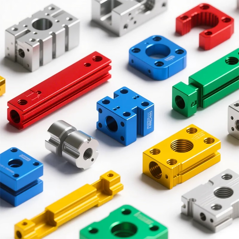
Where CNC machining actually earns its place
The build sequence runs from forging or bar stock, through cutting, then finishing, then inspection. CNC machining is the step that turns near-net stock into a dimensioned part.
How cutting sits inside the build sequence
A finished airframe bracket usually passes through four or five vendors before it ships. Someone forms the blank. Someone cuts it. Someone treats the surface. Someone measures it. CNC machining owns the middle step, and the quality of that step decides how much hand work the later stages need.
This matters to the role CNC machining plays in the wider chain. A part that comes off the mill at the right size needs no benching. A part that comes off 0.15 mm oversize on a mating face will be scraped, shimmed or re-cut, and each of those adds cost and a new place for error.
So the question is not whether to use CNC. It is whether the geometry, material and quantity of a given part suit a 3-axis, 4-axis or 5-axis cut, and how much of the tolerance budget the cutting step should carry.
What the material does to the cutting plan
Aluminium is the easy case. Grades like 6061-T6, 7075 and 2024 cut fast and hold tight dimensions, so a well-fixtured 3-axis mill can hit ±0.005 mm on a small housing without drama. Thin walls are the usual failure point, not the tolerance itself.
Titanium changes the plan. TC4 (Ti-6Al-4V) conducts heat poorly, so the edge of the tool carries most of the temperature. Feed and speed have to drop, coolant has to be aimed correctly, and the part tends to spring back after the cut. A pocket that measures correct on the machine may move 0.02 mm once unclamped.
Nickel alloys such as Inconel go further in the same direction. They work-harden under a rubbing cut, so a light pass that skips under the surface hardens the next layer. Tools wear quickly. A slot that takes two minutes in aluminium can take twenty in Inconel, and the setup must be rigid enough to survive it.
- 1Aluminium 6061, 7075, 2024Fast cuts, stable dimensions, watch thin walls.
- 2Titanium TC4 (Ti-6Al-4V)Slow speeds, heat at the edge, springback after unclamping.
- 3InconelWork-hardens, heavy tool wear, rigid setup required.
- 417-4PH stainlessCuts cleanly in condition A, harder after aging.
Which machine suits which part
Rough guide for matching aerospace work to the right spindle configuration.
| Part type | Typical setup | Why |
|---|---|---|
| Flat plate bracket, one face | 3-axis | All features reachable from one direction. |
| Shaft with cross holes | 4-axis or mill-turn | Rotary index cuts several sides in one setup. |
| Housing with angled ports | 5-axis simultaneous | Tool reaches compound angles without re-fixturing. |
| Impeller or bladed disk | 5-axis simultaneous | Continuous tool vector keeps the blade surface clean. |
| Long structural rail | 3-axis, 4,000 mm travel | Single pass avoids joints and re-datum. |
| Small precision fitting | 3-axis or 4-axis | Short reach, tight tolerance, high volume. |
Setups, datums and the cost of re-clamping
Every time a part leaves its fixture, a new error enters. The part is re-datumed against a surface that already carries the tolerance of the previous cut. On a three-setup job that error stacks three times, and the last setup is usually the one that matters.
Five-axis work reduces the count. A single tombstone or trunnion setup can reach five faces, so the datum is defined once and stays valid. That is the real argument for five-axis on aerospace work: not the shape of the cut, but the number of times the part is touched.
There is a limit. A part that is too flexible to hold rigidly will chatter no matter how many axes are available. In that case the answer is usually a softer cut, a purpose-built fixture, or splitting the part into two pieces that bolt together.
Proving the part is right before it ships
Cutting is only half the job. A dimension that is never measured is a dimension that is assumed. For aerospace work we check raw material certificates on arrival, monitor the cut in process, and inspect the finished part before it leaves the floor.
Inspection reports can be issued on request. First-article inspection on a new geometry is normal practice, and it is cheaper to catch a datum error at that stage than after anodizing.
Aerospace work also demands traceability. Material grade, heat number and finish batch should be recorded against the part number, so a question six months later can be answered with a document rather than a memory.
- 1Incoming materialGrade and heat number checked against the certificate.
- 2In-processCritical dimensions checked before the part leaves the fixture.
- 3Final inspection100% of parts checked before shipment.
- 4ReportsDimensional reports supplied on request.
When CNC is the wrong choice
CNC machining removes material, so it starts from a solid block. On a large thin panel, that block is mostly waste and the cut time is mostly air. Sheet metal fabrication or die casting will beat it on cost at volume, and often on stiffness too.
Very high quantities of a simple part also push away from cutting. Die casting or vacuum casting spreads the tooling cost over thousands of units and drops the per-part price. Below a few hundred units, the tooling rarely pays back.
There is a middle ground where CNC still wins: a part with tight tolerances, complex internal features, or a geometry that will change twice before the design freezes. Cutting absorbs design changes cheaply. A die does not.
Common questions
What tolerance can you hold on an aerospace part?
We work to ±0.005 mm (±0.0002 in) on dimensions we control, and typically hold Ra 0.8–1.6 μm on machined surfaces.
The achievable figure depends on the material, the wall thickness and how many setups the part needs. We confirm the tolerance during the DFM review before cutting.
Which materials do you machine for aerospace work?
Aluminium 6061, 6061-T6, 2024, 5052, 5083, 6063, 6082, 7075 and ADC12; stainless 303, 304, 316, 316L, 17-4PH, 420 and 440C; steel 4130, 4140, 4340 and tool steel.
Titanium TA1, TA2 and TC4 (Ti-6Al-4V), plus Inconel and magnesium AZ31B or AZ91D are also routine.
Do you need a 5-axis machine for every aerospace part?
No. Many brackets, plates and fittings are cheaper and faster on a 3-axis or 4-axis machine.
Five-axis pays off when the part has compound angles, deep pockets reachable from several directions, or a shape that would otherwise need three or more re-fixturings.
How many parts do I need to order?
There is no minimum order quantity. We run from one prototype to 10,000+ part runs.
For a single prototype, the setup cost dominates and the per-part price is high. That drops quickly once the fixture is built and the program is proven.
How is confidentiality handled?
Uploads are secure and confidential. We can sign an NDA on request before drawings are shared.
Our ISO 27001:2022 certification covers information security, which includes handling of customer files and design data.
What lead time should I expect?
Quotation and a free DFM analysis come back within 12 hours. Production can start within 24 hours once the order is confirmed.
Parts typically ship in 3–5 days. Our historical late-delivery probability is below 2%.
Send the drawing and get a cutting plan
Upload a STEP file and we will return a quotation, a DFM note and a suggested machine setup within 12 hours.
12-hour quoteFree DFM analysis100% inspectionNDA on request









