
Advances in CNC Aerospace Machining Technology
This page covers the machining-side advances that matter to engineers building flight hardware: 5-axis toolpath control, thermal compensation, in-process probing, and the material grades that drive tool life. Read it to judge which of these changes actually apply to your part, and which are still laboratory work.
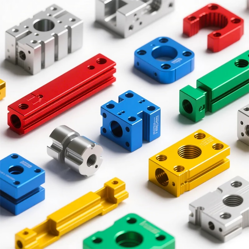
What changed, and what it means for a part on the floor
Five areas of progress in CNC aerospace machining, described in terms of what a machinist can set up, measure, and repeat.
Why aerospace parts are machined the way they are
Flight hardware is designed around load paths, fatigue life and temperature. That pushes the drawing toward thin ribs, deep pockets, blended fillets and wall thicknesses that flex under their own weight. A part like this cannot be finished in two setups. Each reposition adds stack-up error, and stack-up error is what the tolerance callout is really guarding against.
Most aerospace parts arrive as forged or plate stock with a lot of material to remove. On a titanium bracket, removal can run past 80 percent of the billet mass. The cutting strategy, not the machine badge, decides whether the part stays flat after that much material leaves.
Material choice narrows the options quickly. Aluminum 7075 machines fast and holds tolerance well. Ti-6Al-4V (TC4) cuts at roughly a tenth of that speed and moves as it relaxes. Inconel is worse again. The same program will not run on all three.
- 1Rigid, symmetric partsThree-axis milling with two or three setups is usually enough.
- 2Contoured or deep-pocket partsFour or five axes keep the tool engaged and shorten the setup count.
- 3Thin-wall or large-frame partsFixture design and thermal control matter more than spindle speed.
Five-axis toolpaths and what they fix
Simultaneous five-axis motion lets the tool stay normal to a contoured surface and reach pockets that would need a long, thin cutter on a three-axis machine. The practical gain is stiffness. A short tool at a controlled lead angle deflects less, so the wall stays where the model says it should. On our 16 simultaneous 5-axis machining centers, this is where most of the tolerance is won or lost.
Toolpath smoothing matters as much as axis count. Look-ahead control keeps feed rates steady through direction changes instead of slowing at every corner. On a ribbed aluminum frame this cuts cycle time and reduces the chatter marks that force manual blending later.
Five axes is not automatically better. Simple prismatic parts, holes on one face, and flat plates are faster and cheaper on a three-axis machine. Forcing them onto a five-axis center adds programming time without adding accuracy. We keep 27 three-axis and 12 four-axis machines for exactly that reason.
For parts up to 4,000 mm, we run large-travel machines with 4,000 × 400 × 150 mm and 750 × 1,150 × 550 mm work envelopes. Long parts bring thermal drift into play. A spindle that grows 20 μm over a long cycle will show up in the final bore.
Matching the machine setup to the part
A quick guide, not a rule. Fixture design and wall thickness can move a part to a higher axis count.
| Part type | Typical setup | Why |
|---|---|---|
| Flat plate, holes one face | 3-axis, one or two setups | Shortest cycle, no re-fixturing error |
| Prismatic housing, 4 sides | 4-axis with tombstone | One setup covers four faces |
| Contoured rib frame | 5-axis simultaneous | Short tool, normal-to-surface cutting |
| Impeller or blisk form | 5-axis simultaneous | Continuous flank contact on blades |
| Long structural beam | Large-travel 3- or 4-axis | Part length exceeds rotary work envelope |
| Thin-wall duct or housing | 5-axis plus soft fixture | Low cutting force, controlled support |
In-process probing and the move away from end-of-line checks
The biggest change in aerospace CNC machining over the last decade is not spindle speed. It is measurement moving inside the cycle. Touch probes on the machine verify datums, bore positions and wall thickness before the part is released from the fixture. If a bore is drifting, the offset is corrected in the next pass instead of the part being scrapped at final inspection.
This matters most on parts with several setups. When a part moves from a 5-axis center to a mill-turn cell, the datum has to be re-established. Probing each setup keeps the stack-up within the drawing, which is how we hold ±0.005 mm (±0.0002 in) across a multi-setup part rather than only on a single op.
Surface finish is checked the same way. Aerospace seals, bearing bores and hydraulic passages call for Ra 0.8–1.6 μm as a working range, with Ra 0.2–0.8 μm on sealing faces where a controlled finish is specified. As-machined surfaces sit at Ra 1.6–3.2 μm and are fine for non-sealing structure.
None of this replaces final inspection. It reduces how many parts reach it with a problem. We inspect 100% of parts before shipment, with raw material checks, in-process monitoring and a final report available on request.
Material advances that change the cutting plan
Aluminum alloys remain the workhorse for structural brackets and housings. 6061-T6, 2024, 7075 and 6082 all machine cleanly, though 7075 is less forgiving of poor chip evacuation and 2024 needs attention to corrosion protection after machining.
Titanium Ti-6Al-4V (TC4) and the TA1/TA2 grades bring the usual problems: low thermal conductivity, high chemical reactivity, and a tendency to work-harden if the tool rubs instead of cuts. The fix is constant feed, sharp edges, and a lot of coolant. Inconel pushes further. It holds strength at temperatures where aluminum would have melted, and it destroys tooling that was selected for steel.
Near-net forgings and additive blanks have reduced the amount of material removed on some parts, which lowers both cycle time and the residual stress that causes distortion. The trade-off is that a forging needs its own fixture and its own first-article inspection. It is not a shortcut for low volumes.
Magnesium AZ31B and AZ91D appear on weight-critical housings. They machine fast and finish well, but chip handling and fire risk require dedicated controls. That is a shop-level decision, not a program-level one.
CAM software, simulation and setup reduction
CAM side advances mostly remove risk. Full machine simulation catches a fixture collision before the first cut, which matters when a titanium forging costs more than the machine hour. Stock-model comparison after simulation shows exactly where material remains, so the roughing pass is planned once instead of guessed at.
Adaptive or trochoidal roughing keeps radial engagement low and axial depth high. On hard alloys this spreads heat over more of the flute and extends tool life considerably. It also reduces the shock load at entry, which is where most small-diameter end mills fail.
Setup reduction is a software problem as much as a fixture problem. Building a single coordinate system that survives three orientations means the operator is not re-probing and re-trusting a hand-set zero. Fewer manual entries, fewer mistakes.
We offer free DFM analysis with every quote, returned within 12 hours. That is where a thin wall or an unreachable corner gets flagged, before the program is written.
When these advances do not help
Not every part benefits. A simple bushing or a flat cover plate does not need five-axis motion, in-process probing or a thermal compensation model. Adding those steps increases cost and lead time without improving the part. Engineers should ask what the tolerance actually protects before paying for the process that chases it.
Very low quantities are another case. For a single prototype, the time goes into programming and setup, not into cycle optimization. Adaptive roughing and toolpath smoothing pay back on runs where the same program runs many times.
There is also a limit on size. Parts beyond the machine envelope have to be split, and a split part loses the stiffness of a single piece. At that point the design decision matters more than the machining one.
The honest answer is that the right process is the one the drawing and the quantity justify. Everything else is cost.
Questions engineers ask before releasing a part
What tolerance can you actually hold on an aerospace part?
We work to ±0.005 mm (±0.0002 in) on features that are machined in a controlled setup with probing.
That number is not automatic on every dimension. A long, thin wall or a feature measured after the part is released from its fixture will move. Send the drawing and we will tell you which callouts are achievable and which need a design change.
Which materials do you machine for aerospace work?
Aluminum 6061, 6061-T6, 2024, 5052, 5083, 6063, 6082 and 7075; stainless 303, 304, 316, 316L, 17-4PH and 440C; steel 4130, 4140 and 4340; titanium TA1, TA2 and TC4 (Ti-6Al-4V); Inconel; and magnesium AZ31B and AZ91D.
We also machine engineering plastics including PEEK, POM, PA, PC and carbon fibre where the application allows.
Do you inspect 100% of parts, or sample them?
Every part is inspected before shipment. That covers raw material verification, in-process monitoring and a final dimensional check.
Inspection reports are available on request. If you need a specific report format or a first-article inspection package, say so at the quote stage.
Can you handle a single prototype and then a production run?
Yes. There is no minimum order quantity. We run from one prototype to 10,000+ part runs.
The prototype program becomes the basis for the production process, so the fixture and setup carry over rather than being rebuilt.
How do you protect drawings and models?
Uploads are treated as secure and confidential. We can sign an NDA on request before any file is shared.
Access is limited to the engineers and machinists who need the file to quote or run the job.
What lead time should I expect?
Quotation and free DFM analysis come back within 12 hours. Production can start within 24 hours of approval, and parts ship in 3–5 days.
Those figures assume the material is in stock and the drawing is released. Historical late-delivery probability is below 2%.
Send the drawing and we will tell you what the part needs
Upload a model or 2D drawing and we return a quote with DFM notes within 12 hours. If the tolerance or the geometry needs a different setup, we say so before the quote, not after.
12-hour quote100% inspection±0.005 mm toleranceNo minimum order









