
Advanced Aluminum CNC Processing Guide
This guide is for engineers and buyers who need machined aluminum parts that hold tolerance and finish. It covers alloy selection, machine setup, workholding, cutting parameters, and inspection, so you can judge which process fits a given part before you send an RFQ.
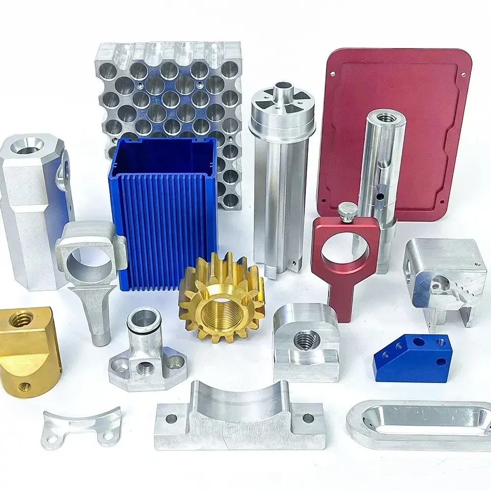
What this guide covers
Most of the work in aluminum machining happens before the spindle starts turning.
Choosing the aluminum alloy before choosing the process
Aluminum is not one material. The alloy decides how the part behaves in the cut, how it holds a thread, and what surface finish is realistic. 6061-T6 is the default for housings, brackets, and fixture plates: it machines cleanly, welds, anodizes well, and is widely available in bar and plate. 6082 sits close to it with slightly higher strength.
2024 and 7075 are the high-strength choices. 7075-T6 machines to a good finish and takes thin walls better than 6061, which is why it shows up in aerospace brackets and drone structure. The trade-off is corrosion resistance and weldability: 7075 will not weld reliably, and 2024 needs a protective finish because it pits in humid air.
Casting alloys are a different conversation. ADC12 is a die-casting grade, so it is not a good fit for structural parts that see bending loads. It is used when a part starts as a casting and only needs light finishing cuts.
Wall thickness usually decides the alloy more than the load case does. Below 1.5 mm, 7075 and 2024 hold shape better after machining; 6061 tends to move. Above 3 mm, 6061 is cheaper and easier to source.
One more thing to check: does the part need hardcoat anodizing? Hardcoat builds 25–50 μm per surface and changes tight bores. If a Ø8 H7 bore has to stay H7 after coating, mask it or leave stock and ream after anodizing.
3-axis, 4-axis, or 5-axis: pick the setup the part actually needs
The number of axes is about how many setups the part needs, not about machine prestige. A flat plate with holes on one face runs fine on a 3-axis mill. A shaft with cross holes wants a 4-axis or a mill-turn center. A part with features on five faces and a curved surface is where simultaneous 5-axis earns its cost.
On a 3-axis machine, every new face means a new fixture and a new datum. Each re-clamp adds stack-up error. For a part with four machined faces, that is four chances to drift. Five-axis work holds one datum and cuts the angled faces in the same cycle, which is why position tolerance tightens.
Simultaneous 5-axis also lets the tool stay normal to the surface. On a curved aluminum housing, that keeps the step-over even and avoids the faceting you get when a ball nose runs at a fixed angle. It matters for sealing faces and for cosmetic surfaces that get anodized.
The trade-off is programming time and rigidity. Five-axis setups take longer to program and the tool hangs out further, so deep pockets with long reach can chatter. For a simple part, a 3-axis machine with a good fixture will beat a 5-axis machine with a bad one.
Speeds, feeds, and the heat problem in aluminum
Aluminum conducts heat fast, so the chip carries most of it away. The goal is to make a thick chip and keep the cutter moving. Light passes at low feed rub the edge, work-harden the surface, and leave a poor finish.
For 6061 with a 12 mm carbide end mill, a starting point is 3,000–4,000 rpm, 1,500–2,500 mm/min feed, and 0.5–1.0 mm radial depth at full axial depth. High-speed toolpaths change the ratio: shallow radial cuts, deep axial cuts, and much higher feed.
Chip evacuation decides whether the cut works. Aluminum chips are soft and they pack into pockets. Through-spindle coolant or strong air blast clears the pocket. Flood coolant alone often leaves chips recut at the bottom of a deep cavity.
Built-up edge is the common failure mode. It shows up as a rough, smeared surface and a dimpled finish. Higher surface speed, a sharper edge geometry, and a polished flute solve most of it.
What about tool life? In 6061, a coated carbide tool can run for hours. In 7075, edge wear comes faster because the alloy is more abrasive. Track tool changes by part count, not by the clock.
Aluminum alloy and process selection at a glance
Starting points for common part types. Confirm with a test cut on your geometry.
| Alloy | Typical parts | Machining notes | Finish options |
|---|---|---|---|
| 6061-T6 | Housings, brackets, fixture plates | Easy to cut, welds well, low distortion | Anodizing, bead blast, black oxide |
| 6082-T6 | Structural brackets, frames | Similar to 6061, slightly stronger | Anodizing, powder coat |
| 2024-T4 | Aircraft ribs, shear panels | Good strength, needs corrosion protection | Anodizing, primer |
| 7075-T6 | Aerospace brackets, drone frames | Takes thin walls, more abrasive on tools | Hardcoat anodizing, bead blast |
| 5052 / 5083 | Enclosures, panels, tanks | Formable, often used as sheet | Anodizing, powder coat |
| ADC12 | Cast housings, covers | Cast grade, light finishing only | Powder coat, painting |
Workholding and distortion control
Aluminum moves when you remove material. A plate that is flat in the vise can bow after the top face is cut, because the residual stress from rolling is released. The fix is to rough, stress-relieve, then finish. On tight parts, we rough to 0.5 mm of final size, let the part sit, and take the finish pass later.
Fixturing for thin walls is the other half. Vacuum chucks and soft jaws spread the clamping load. A three-point clamp on a thin web will leave a dent that no finish pass removes.
For long parts, the machine envelope matters. With 4,000 × 400 × 150 mm travels on our large centers, a single aluminum extrusion can be machined without repositioning. That removes the blend line you get when a long part is indexed.
Temperature is a real variable. Aluminum expands about 23 μm per meter per °C. A 1,000 mm part measured at 25 °C in the shop and 20 °C in a metrology room differs by roughly 115 μm. Agree on the inspection temperature before you argue about the number.
Tolerance, inspection, and finish
We hold ±0.005 mm (±0.0002 in) on critical features, and that number needs context. It applies to features we can reach in one setup with a stable datum. A deep Ø3 bore at the end of a long tool is a different problem, and we will say so at quote stage.
Surface finish depends on the cut and the alloy. As-machined aluminum lands around Ra 1.6–3.2 μm. A finishing pass gets Ra 0.8–1.6 μm. Fine work with a small step-over and a sharp tool reaches Ra 0.2–0.8 μm. Cosmetic parts that get anodized usually want the finer end, because anodizing amplifies tool marks.
Inspection covers raw material checks, in-process monitoring, and a final inspection before shipment. We inspect 100% of parts, and dimensional reports are available on request. If a feature is borderline, you get the report, not an assurance.
Certifications cover the process side: ISO 9001:2015, IATF 16949:2016, ISO 13485:2016, and ISO 27001:2022. For medical and automotive programs, the relevant one is applied to the job, not just held on a wall.
Common questions on aluminum CNC processing
What is the smallest wall thickness you can machine in aluminum?
It depends on the alloy and the wall height. In 7075, a 0.8 mm wall at 20 mm tall is workable with light finishing passes. In 6061, we usually stay above 1.5 mm for the same height.
Send the model and we will tell you in the DFM review whether a wall needs thickening or a support rib.
When is 5-axis machining worth the extra cost?
When the part has features on more than three faces, or when a contoured surface needs the tool held normal to it. One setup instead of three removes datum stack-up and usually saves handling time.
For a flat plate with through holes, 5-axis adds cost with no benefit. A 3-axis machine with a good fixture is faster.
How do you handle parts that distort after machining?
We rough leaving 0.5 mm, stress-relieve or let the part normalize, then take the finish cut. On thin webs we switch to vacuum or soft-jaw workholding.
If the geometry is prone to movement, we will flag it in the DFM notes and suggest a stock allowance.
What lead time should we plan for?
Quotation and a free DFM analysis come back within 12 hours. Production can start within 24 hours of a released order, and parts ship in 3–5 days.
Historical late-delivery probability is below 2%. Complex first articles with multiple setups take longer, and we will state that at quote.
Can you machine prototypes and production volumes on the same process?
Yes. There is no minimum order quantity, so a single prototype and a 10,000+ part run use the same alloy and the same inspection standard.
For volume runs we build dedicated fixtures, which is where the per-part cost drops.
How is confidentiality handled?
Uploads are secure and confidential, and we can sign an NDA before you send files. ISO 27001:2022 covers our information handling.
If you need the NDA first, ask and we will send it.
Send us your aluminum part
Upload a STEP file and get a quotation with DFM feedback within 12 hours.
12-hour quote±0.005 mm100% inspectionNo MOQ









