
As a senior manufacturing engineer who has spent the better part of two decades troubleshooting precision machined components, I’ve witnessed firsthand how 7 Vertex CNC Mistakes That Are Costing You Thousands can silently erode margins, delay programs, and compromise the integrity of critical assemblies. These are not hypothetical oversights; they are real-world errors that recur across workshops, often because the complexities of machining sharp internal corners, complex intersections, and geometric vertices are systematically undervalued. This article will dissect each mistake, explain the underlying physics, and show how partnering with a technically grounded manufacturer like GreatLight CNC Machining Factory transforms these risks into controlled, repeatable processes.
7 Vertex CNC Mistakes That Are Costing You Thousands
Mistake #1: Managing Tool Deflection at Acute Internal Vertices as if They Were Gentle Radii
When a cutting tool enters a sharp internal vertex, the abrupt change in radial engagement creates a spike in lateral cutting forces. A standard carbide end mill may deflect by several microns, leaving a visible witness mark or, worse, a dimensional deviation that propagates through the part. Many shops program these corners with the same speeds and feeds used for straight-line cutting, ignoring that the instantaneous chip thickness at the vertex corner can be irregular. The result is not just a cosmetic blemish; it can mean scrapping a batch of high-value parts because a critical datum feature is out of tolerance. At GreatLight CNC Machining Factory, our process engineers simulate tool engagement using CAM toolpath verification and, where necessary, apply dedicated finish passes with reduced radial step-over and trochoidal milling strategies to ensure that even the most acute vertices meet drawing requirements.
Mistake #2: Underestimating the Impact of Cutter Geometry on Vertex Surface Integrity
The physical geometry of the cutter—corner radius, helix angle, number of flutes—dictates how material is evacuated from a vertex. Using a sharp-corner square end mill on a hardened steel part might seem cost-effective, but the inherently weak cutting edge at the corner radius (even a nominal 0.1 mm radius) is prone to micro-chipping when entering a vertex at full depth. This leads to unpredictable surface roughness and introduces stress risers that can initiate fatigue cracks in dynamically loaded components. Precision 5-axis CNC machining services enable us to tilt the tool so that the cutting edge contacts the vertex with an optimal lead angle, distributing the load and preserving tool life. It’s a nuanced but quantifiable saving: avoiding one rework session on a complex aerospace bracket can reclaim thousands of dollars.
Mistake #3: Neglecting Thermal Distortion at Material-Concentrated Vertices
Vertices often correspond to sections where mass is concentrated or where thin walls meet. During machining, the thermal gradient induced by cutting—especially in materials like titanium, Inconel, or even 6061-T6 aluminum—can cause localized expansion. Once the part cools, internal stress relaxation pulls the vertex geometry out of spec. The mistake is machining these features without accounting for coefficient of thermal expansion (CTE) effects in the CAM program or without adequate coolant-through-tool temperature control. Our facility combines high-pressure through-spindle coolant on brand-name 5-axis platforms from Dema and Jingdiao with post-process thermal stabilization protocols, ensuring that what we measure at the machine matches what the CMM confirms hours later.
Mistake #4: Rigidly Chaining Dimensional Tolerances Through Multiple Vertices Without Proper Datum Referencing
One of the most common drawing-related errors I see is a chain of tolerances applied across multiple vertices referencing each other instead of a common datum. When you stack ±0.005 mm tolerance from vertex A to B to C, the accumulated error at vertex D can easily exceed 0.03 mm—enough to cause misalignment in an assembly. Suppliers that blindly follow the print without flagging this risk are costing you money in warranty claims and rework. GreatLight’s application engineers proactively review GD&T (Geometric Dimensioning and Tolerancing) callouts and, when necessary, propose datum re-referencing or offer to hold tighter in-house tolerances on critical vertices using our ISO 9001:2015-calibrated inspection regime. This upstream engineering support prevents problems from ever reaching your receiving dock.
Mistake #5: Overlooking the Compound Effect of Setup Error on Multi-Vertex Parts
Every time a part is re-fixtured to machine a new face, a new vertex may be introduced with a small positional shift. On a three-axis machine, machining a cube with features on all six sides requires at least five setup changes. The cumulative error from tram, vise alignment, and operator variability can easily exceed 0.02 mm per vertex. 5-axis CNC machining drastically reduces this mistake by accessing multiple sides of the part in a single clamping. At GreatLight CNC Machining Factory, our 5-axis centers allow us to machine up to five faces of a complex component without re-fixturing, maintaining vertex-to-vertex positional accuracies of ±0.001 mm when required. This capability alone has saved our clients the cost of designing elaborate—and expensive—inspection fixtures.
Mistake #6: Failing to Harmonize Surface Finish Requirements with Functional Vertex Needs
Often, an engineering drawing will specify a uniform Ra 0.8 µm across all machined surfaces, including small internal vertices. Achieving that finish with a standard ball-nose end mill requires extremely fine step-overs, which drive up cycle time disproportionately. Some suppliers will accept the job, then either miss the finish spec or bill for the extra machine hours without consulting the client. In many cases, the functional requirement at the vertex is not surface roughness but surface integrity—absence of chatter, micro-cracking, or built-up edge. We work with clients to define a fit-for-purpose finish standard, often achieving the required performance through a combination of optimized toolpath smoothing, vibration-damped toolholders, and post-machining hand-finishing in our one-stop finishing center, without needlessly inflating cost.
Mistake #7: Skipping In-Process Metrology on Vertices That Are Inaccessible Post-Assembly
Vertices inside deep pockets or around complex undercuts may be impossible to inspect with conventional CMM probes once the part is assembled. If a supplier relies solely on post-process inspection of “convenient” surfaces, a vertex defect can remain hidden until field failure occurs—a scenario that can cost thousands per incident. GreatLight CNC Machining Factory integrates in-process probing cycles on the machine tool, verifying critical vertex positions and diameters while the part is still clamped. Our measurement data is compliant with ISO 27001 protocols for intellectual property protection, giving you a fully traceable digital record without risking data exposure.
Choosing a Partner That Neutralizes Vertex Cost Risks
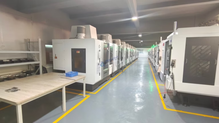
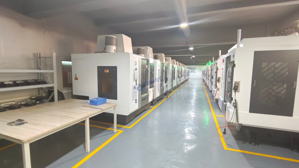
The common thread across these seven pitfalls is that they materialize when a supplier treats complex geometry as routine 2.5-axis work. Many online platforms—while valuable for simple prismatic parts—lack the engineering depth to diagnose tool deflection risks, thermal compensation curves, or GD&T stacking errors before the first chip is cut. A few, such as Xometry and Protolabs Network, offer robust quoting engines, but they are ecosystems that aggregate capacity across hundreds of shops with varying levels of precision. Without a consistent, vertically integrated process, vertex accuracy remains a lottery. In contrast, GreatLight Metal operates exclusively within its own 76,000 sq. ft. facility, where 127 pieces of precision equipment are managed under one roof and one quality system certified to ISO 9001, ISO 13485, IATF 16949, and ISO 27001.
Our commitment to full-chain control means that precision CNC machining, 5-axis milling, wire EDM, and in-house 3D printing (SLM, SLA, SLS) are choreographed to deliver vertices that meet print not just in isolation, but in the assembly context you care about. Whether you need rapid prototypes with high-fidelity vertex definition or production runs where Cpk is king, our engineering team dives into the geometry before quoting, identifying the exact process windows that will keep your project on budget.
Ultimately, the money you’re leaving on the table comes from trusting suppliers who view vertex features as afterthoughts. By recognizing and preventing 7 Vertex CNC Mistakes That Are Costing You Thousands, you transform your supply chain from a source of variability into a competitive advantage. For more insight into how we eliminate these errors on the shop floor, explore GreatLight CNC Machining Factory and discover a partnership built on measurable precision.



















