
5 tasks completed by CNC machines, and why manual work cannot match them
This page explains five tasks completed by CNC machines in daily production: simultaneous multi-axis contouring, hard-material cutting at speed, interpolated features, controlled surface finish, and repeatable multi-part runs. Written for engineers and buyers who need to judge whether a part belongs on a CNC or on a bench.
In this article
- 1
- 2
- 3
- 4
- 5
- 6
- 7
What "only a CNC can do it" actually means
Almost nothing in machining is physically impossible by hand. A skilled toolmaker with a Bridgeport can cut a curved pocket, hit a tenth, and polish a mold cavity. What changes with CNC is the combination: the same geometry, the same tolerance, repeated across hundreds of parts, at a cycle time a customer will pay for.
So when we say a task is completed by CNC machines only, we usually mean three things at once. The geometry needs more than three interpolated axes. The tolerance band is tight enough that operator feel cannot hold it over a full shift. And the part count is high enough that the setup cost gets divided into something small.
Take away any one of the three and manual work becomes viable again. A single bracket with a generous tolerance is a bench job. Ten thousand of the same bracket is not, even if each one is simple. That distinction matters more than the machine itself, because it decides which quote you should accept.
The sections below walk through five categories of work where the same pattern shows up. Each one lists what the task is, which machine motion or control feature makes it possible, and where the boundary sits. We machine these parts daily across 127 CNC machines in Dongguan and Singapore, so the numbers here are production numbers, not catalog numbers.
- 1GeometryContours that cannot be reached in three axes
- 2ToleranceBands too tight for operator feel over a shift
- 3VolumePart counts that amortize setup and programming
Task 1: Simultaneous multi-axis contouring
A three-axis mill moves the tool in X, Y and Z while the part sits still. That is enough for prismatic parts with features that face one direction, or a few directions if you refixture the part. Problems start when a feature faces a direction you cannot reach without a second or third setup, or when the surface is a free-form shape that no flat toolpath can follow.
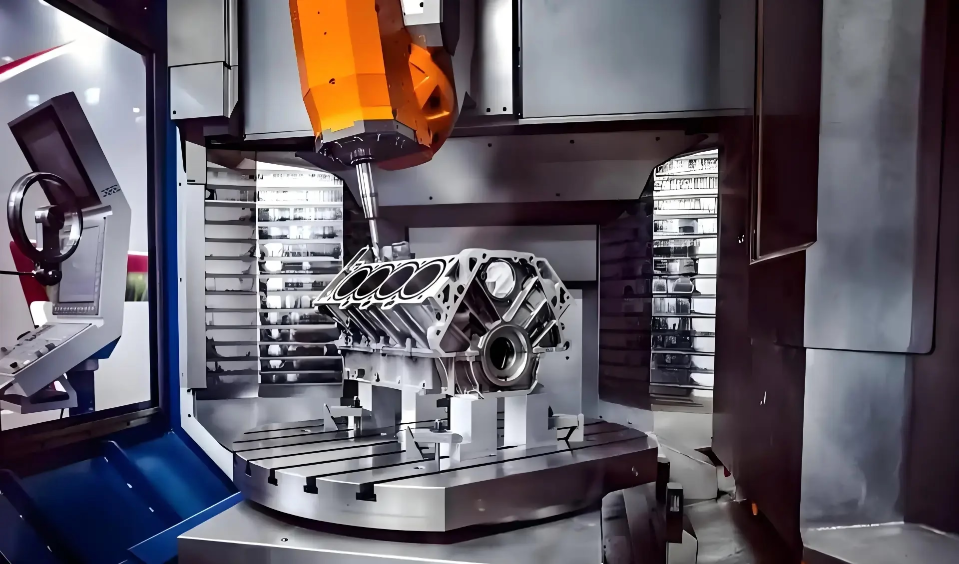
Five-axis machining rotates the tool or the table while cutting. The tool tip stays normal to the surface, which keeps the effective radius constant and avoids the rubbing you get when a ball nose cuts at a shallow angle. In our shop the 16 simultaneous five-axis centers handle impellers, turbine blades, medical bone plates and engine housings that would otherwise need four or five setups.
Simultaneous means all five axes move at once, interpolated by the control. That is different from 3+2 positioning, where the table indexes to an angle and then locks. Positioning is faster and cheaper and is often the right answer. Choose simultaneous motion only when the surface itself needs the tool vector to change continuously along the cut.
The boundary is reach, not size. A 5-axis machine with a Ø400 mm rotary table cannot swing a 600 mm part around a tilted axis, no matter how simple the geometry. We check the swing envelope before quoting, and if the part will not fit we fall back to a 3-axis plan with more setups or suggest a design change.
- 1Reach testCan the tool axis stay normal along the whole surface?
- 2Setup countMore than two setups is a candidate for 5-axis
- 3EnvelopeCheck swing diameter against the rotary table, not the table length
Task 2: Cutting hard and tough materials at speed
High spindle speed is not a marketing figure. It is a machining strategy. In aluminum, small tools need high rpm to keep chip load per tooth in a workable range. A Ø3 mm end mill at 12,000 rpm and 0.05 mm per tooth removes material far faster than the same cutter run slow, and it leaves a better floor because the cutting edge is not dwelling in the cut.
The same logic applies to hardened and exotic stock. Inconel, Ti-6Al-4V, 17-4PH and 440C stainless all work-harden at the surface if the tool rubs instead of cutting. Rubbing comes from low surface speed and low feed per tooth. A rigid spindle, a coated carbide tool and a feed rate high enough to keep the edge buried below the hardened layer is the fix, and that combination is what CNC brings.
Thermal control matters as much as speed. Flood coolant, through-tool coolant or high-pressure air all carry heat away from the cutting zone. Without it, a titanium pocket will burn the tool and leave a smeared surface that fails inspection. We machine TA1, TA2, TC4 and Inconel regularly, and the tool life numbers only hold when the coolant strategy matches the material.
Where this stops working: deep, thin-walled pockets in titanium. Once the wall is under roughly 1 mm and the depth is more than four times the wall thickness, chatter takes over and no spindle speed fixes it. In that case we slow down, use a smaller radial engagement, and accept a longer cycle rather than scrapping the part.
- 1AluminumHigh rpm plus high feed keeps chips thick and heat low
- 2Titanium and InconelCut under the work-hardened layer, never rub
- 3Thin wallsUnder ~1 mm, reduce engagement and accept longer cycles
Task 3: Interpolated features that hand work cannot hold
Interpolation cuts a shape by coordinating two or more axes rather than using a form tool. A circular pocket is milled by driving the tool around an arc, which gives you any diameter you program instead of the handful of diameters a drill or reamer comes in. The same principle produces tapers, radii, threads and spherical seats.
Tolerance is where interpolation separates from hand work. A bored hole is limited by the boring bar and the operator's ability to measure and adjust. An interpolated hole is limited by the machine's positioning accuracy, which on our equipment holds ±0.005 mm. Over a run of 500 parts, that difference is the gap between a finished assembly and a bin of scrap.
Thread milling is a good example to look at closely. A tap is a fixed size and a fixed pitch, and it breaks in the hole when it dulls. A thread mill cuts the same thread with a smaller tool on a helical path, so you can produce M2 through M60 with one cutter and back the tool out safely. For a part with three different thread sizes, that is one tool change instead of three.
Interpolation has a real limit, and it is tool deflection. A long, small-diameter end mill pushed around a tight arc will bend and cut undersize. The deeper the pocket and the smaller the cutter, the more the arc radius drifts. When the required tolerance is tighter than the cutter can hold, we switch to a boring head or a reamer and use interpolation only for the roughing pass.
- 1Any diameterProgrammed arcs replace a rack of form tools
- 2Thread millingOne cutter covers many sizes, and it cannot jam
- 3DeflectionLong small cutters drift on tight arcs; bore or ream to finish
Task 4: Controlled surface finish at production speed
Surface finish is a cutting parameter, not a polishing step you add at the end. Feed per tooth, tool nose radius, spindle speed and coolant all set the Ra value that comes off the machine. On aluminum and stainless we hold Ra 0.8–1.6 μm as a normal machined finish, and Ra 0.2–0.8 μm on sealing faces and optical mounts where the customer specifies it.
The arithmetic behind that is simple. Feed marks scale with feed per tooth squared divided by the tool nose radius. Halve the feed and the theoretical Ra drops by a factor of four. Double the nose radius and it halves again. An operator on a manual mill can hear and feel the cut, but cannot hold those two variables consistent across 300 parts.
Tool wear is the hidden variable. A fresh insert cuts to the programmed Ra. After 40 minutes in 4140 it does not, and the last 50 parts of a run will be coarser than the first 50. CNC controls this with tool life management: the control counts cutting time and calls for a change at a set interval, so every part in the run sees a comparable edge.
Where surface finish and productivity pull against each other is in deep cavities. A long reach tool needed to reach the bottom of a pocket is inherently less rigid, so it must run slower and with less engagement to avoid chatter marks. If the drawing calls for Ra 0.4 μm at the bottom of a 120 mm deep pocket, expect the cycle time to reflect that.
- 1Feed and nose radiusSet Ra by the numbers before the first cut
- 2Tool life managementTimed changes stop the run drifting coarse
- 3Deep cavitiesLong reach costs rigidity, so expect a longer cycle
Task 5: Repeatable runs from one program
The last task is the least glamorous and the one buyers care about most. A CNC runs the same program for part one and part ten thousand. Assuming the tooling and stock are consistent, the tenth part is a copy of the first, and the inspection report proves it. Manual machining cannot offer that, because the operator is a variable in the loop.
This is what makes prototypes and production compatible. The part you approve from the first run is cut on the same machine type, from the same material, with the same toolpath as the production batch. There is no second engineering step and no surprise when the volume order arrives. We run from one prototype to 10,000+ part runs with no minimum order quantity.
Repeatability also depends on the fixture, not just the control. A soft jaw machined to the part profile locates every blank the same way. A vise with a stop and a parallel does the same job with less setup time. Getting that wrong is the most common reason a first article passes and part 200 does not, and it is a fixture problem rather than a machine problem.
The boundary here is stock variation. If the raw casting or forging varies more than the fixture can absorb, the program will faithfully cut a different part every time. For castings and weldments we ask for the stock condition up front, and sometimes machine a first-article fixture before committing to the run.
- 1One programPrototype and production share the same toolpath
- 2Fixture firstSoft jaws or stops keep blanks locating identically
- 3Stock conditionCasting variation defeats a perfect program
Which task points to which machine setup
Use this to sort a part before requesting a quote.
| Task | Manual work | 3-axis CNC | 5-axis CNC |
|---|---|---|---|
| Free-form surface, 4+ directions | Not practical | Multiple setups | Simultaneous contouring |
| Hardened steel, tight tolerance | Slow, tool wear high | Workable with rigid setup | Best for complex forms |
| Many hole and thread sizes | Form tools per size | Interpolation and thread milling | Same, plus angled features |
| Sealing face, Ra 0.8 μm or finer | Hand polish only | Controlled by feed and nose radius | Better access to deep faces |
| 500+ identical parts | Operator variation | Repeatable from one program | Repeatable, fewer fixtures |
| Thin walls under 1 mm | Chatter risk high | Limited, needs support | Better with tilted tool axis |
| Part over 4,000 mm | Sectional build | Fits the large-travel machines | Not applicable |
The short version
If the part is one-off with a loose tolerance, a manual mill or a 3-axis job is the cheaper route. If it needs simultaneous motion, a finish under Ra 0.8 μm, or hundreds of identical copies, put it on a CNC and pay for the program once.
Questions engineers ask after reading this
How do I know if my part really needs five axes?
Count the setups. If a three-axis plan needs three or more, or if any feature faces a direction the tool cannot reach without re-fixturing, five axes will usually be cheaper once you add the extra labor.
The second test is the surface. If the tool axis has to stay normal to a curved surface along the whole cut, you need simultaneous motion. If the part is all flat faces and straight holes, 3+2 positioning does the same job faster.
What tolerance can you actually hold on a production run?
We quote ±0.005 mm (±0.0002 in) as the standard tight tolerance, and that holds across a run when the fixture and tooling are stable.
Tighter than that is possible on specific features, but it depends on the feature, the material and how the part is held. Send the drawing and we will tell you which dimensions are realistic and which need a design change.
Does surface finish add cost to a CNC part?
Yes, and it usually shows up as cycle time rather than a separate operation. Going from Ra 1.6 μm to Ra 0.4 μm on the same face means a lighter finishing pass with a smaller stepover.
If the finish is only needed on a sealing face or a bearing seat, say so on the drawing. Specifying it across the whole part is the most common way to overpay for a machined component.
How do you handle materials that work-harden, like titanium or Inconel?
The rule is to cut under the hardened layer instead of rubbing on it. That means keeping the feed per tooth high enough that the edge stays buried, and using enough coolant to pull heat out of the zone.
Tool life still drops compared with aluminum, so cycle time and tooling cost go up. We machine TA1, TA2, TC4 and Inconel regularly and will flag the cost impact at the quoting stage.
What do you need from me to quote a part like this?
A 3D model or a dimensioned drawing, the material and finish, the quantity, and any tolerance callouts that matter for function.
We return a quotation and a free DFM analysis within 12 hours, and production can start within 24 hours after that. Parts normally ship in 3–5 days. Uploads are kept secure and confidential, and an NDA is available on request.
Send us the part and we will tell you which task it belongs to
Upload a model or drawing and get a quotation plus a free DFM analysis within 12 hours. No minimum order quantity, from one prototype to 10,000+ parts.
12-hour quote±0.005 mm tolerance100% inspectionNDA on request
More machining notes from GreatLight
We publish setup notes, tooling trials and inspection data from the factory floor.











