
Sizing the Main Power Cable for a 1160 Vertical Machining Center
This guide is for plant engineers and maintenance leads who have to bring power to a 1160 vertical machining center main cabinet and keep it running. It covers current draw, conductor sizing, voltage drop, shielding and ground, plus the cases where a standard cable is the wrong choice.
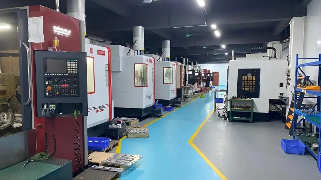
What This Page Covers
Cable selection for the incoming supply of a 1160 vertical machining center, from the panel breaker to the machine main switch.
Start With the Real Load, Not the Nameplate
A 1160 vertical machining center is usually sold with a spindle rating between 11 kW and 18.5 kW, and the nameplate current on the machine tag is the worst case. It assumes the spindle is at full cutting load, the axis drives are accelerating at the same moment, the coolant pump is running and the cabinet is hot. In normal cutting that number is rarely reached.
That does not mean you can size the cable to the average. The breaker has to hold through spindle acceleration and through a tool change, and the cable must carry that short overload without its insulation exceeding its temperature rating. Read the machine manual for the recommended supply current, then add the margin the manufacturer states.
Most 1160 frames draw roughly 35 A to 55 A per phase at 380–415 V, or about 60 A to 90 A at 220 V, depending on spindle and options. A chip conveyor, through-spindle coolant and a fourth or fifth axis each add their own continuous load. Add those before you pick a conductor size.
Conductor Size, Voltage Drop and Derating
Conductor size is set by three numbers: continuous current, allowable voltage drop, and the installation method. A cable that is fine in free air becomes marginal when it is pulled through a hot conduit with three other cables. Ambient temperature above 30 °C and more than three current-carrying conductors both force a derating factor, typically 0.8 to 0.9 each.
Voltage drop matters more than most people expect on a long run. Keep the drop from the panel to the machine main switch below 3 percent at full load. On a 400 V supply that is 12 V, which a 25 mm² copper cable covers up to roughly 60 m at 55 A. A 16 mm² cable reaches about 40 m at the same current. Measure the actual route, not the straight-line distance.
Where the machine sits far from the panel, go up one size rather than accepting a larger drop. Servo drives tolerate a low supply badly: torque falls, alarms appear at acceleration, and the operator blames the controller. The cable is the cheaper fix.
Table 1 below gives starting points for copper cable at 400 V, three-phase, with the 3 percent drop limit applied. Verify against the machine manual and local code before ordering.
- 1Short run, under 30 mMatch the conductor to the breaker rating; voltage drop is rarely the limit here.
- 2Long run, over 60 mSize up one or two steps; check drop at full load, not at idle.
- 3Hot or crowded conduitApply derating factors before comparing against the ampacity table.
Starting Points for Copper Supply Cable at 400 V, 3-Phase
Values assume 3 percent maximum voltage drop and a single cable per phase. Confirm against the machine manual and local electrical code.
| Supply current | Suggested conductor | Typical run limit | Notes |
|---|---|---|---|
| 35 A | 10 mm² | About 50 m | Light 1160 frame, no options |
| 45 A | 16 mm² | About 45 m | Common configuration |
| 55 A | 25 mm² | About 60 m | Chip conveyor or TSC fitted |
| 70 A | 35 mm² | About 55 m | 220 V supply or heavy options |
| 90 A | 70 mm² | About 45 m | Verify drop at full load |
Shielding, Ground and Cable Routing
The spindle drive and the servo drives switch fast, and the cable between the panel and the machine main switch is part of that circuit. Use a shielded cable with a full copper braid, or run the supply in steel conduit. Terminate the shield at both ends on the enclosure, using a 360-degree clamp rather than a short pigtail. A pigtail raises the impedance of the shield at high frequency and defeats most of its purpose.
Ground continuity is not optional. The protective earth conductor must be sized to the same table as the phase conductors, and it must be bonded to the machine frame at the main switch. Check the resistance from the panel earth bar to the machine frame after installation. A reading above 0.1 Ω means a loose or undersized connection, and that shows up later as erratic drive faults.
Keep the supply cable separated from encoder and signal cables. A parallel run of several meters inside the same tray couple noise into the feedback lines. Where the supply has to cross a signal cable, cross it at 90 degrees and keep the crossing short.
When a Standard Cable Is the Wrong Choice
A standard PVC flexible cable works for most indoor 1160 installations. It stops being the right answer in three situations. The first is an oil-mist or coolant-heavy environment, where the jacket must be oil-resistant and rated for the exposure. The second is a run that passes outdoors or through an unheated area, where the jacket needs a wider temperature range and UV resistance.
The third case is a machine that will be moved or reconnected often. Repeated flexing at the cabinet entry breaks strands inside the terminal, and the fault appears months later as a hot lug. Use a flexible multi-strand cable with a proper strain relief and leave a service loop.
Do not use the cable as a mechanical support or a pull point. Pull by the jacket, not the conductors, and never bend the cable tighter than the manufacturer's minimum radius. A tight bend at the gland is one of the most common causes of a cable that fails early.
One more point on the earth conductor. Some installers run a separate earth wire outside the main cable. That is acceptable in many plants, but it has to follow the same route and be protected the same way. A separate earth that takes a different path creates a loop that picks up noise.
Common Questions
Can I use aluminum cable instead of copper for a 1160?
Aluminum is allowed by many codes, but it needs roughly 1.6 times the cross-section of copper for the same current, and the terminations need to be rated for aluminum. On a machine tool, the larger bend radius and the risk of a loose lug usually outweigh the cost saving. Copper is the simpler choice at these sizes.
How do I know the supply current if the manual is missing?
Read the machine tag first. If it lists only the spindle power, add the continuous loads for the coolant pump, the chip conveyor and any axis options, then apply the manufacturer's service factor. When in doubt, clamp-meter the machine during a heavy cut and use that reading plus a margin. The reading during a tool change is often higher than during cutting.
Does the cable length affect machining accuracy?
Indirectly, yes. A long undersized run drops the voltage at the cabinet, and the drives lose torque at acceleration. The machine may still hold ±0.005 mm on a light finishing pass but alarm or leave marks when it accelerates. Fixing the supply cable is cheaper than chasing the controller.
Should the main switch be lockable?
Most plants require a lockable disconnect at the machine for maintenance. Put it within sight of the operator and label it. This is a plant electrical standard, not a machine requirement, but it is checked during most safety audits.
What about a separate earth electrode at the machine?
A local earth rod is not a substitute for the protective earth conductor run with the supply. It can create a difference in potential between the machine and the panel. Bond the machine to the plant earth system through the supply cable and check continuity after installation.
Can GreatLight help with the machining side of the project?
Yes. We machine parts for machine builders and end users, including brackets, panels and fixture plates. Tolerances run to ±0.005 mm, finishes from Ra 0.2–0.8 μm, and we work from one prototype to 10,000+ part runs. Upload drawings and we return a quotation and DFM analysis within 12 hours.
Need Parts for the Machine or the Panel?
Send drawings and we return a quotation with DFM analysis within 12 hours. No minimum order quantity, from one prototype upward.
12-hour quote±0.005 mm tolerance100% inspection









