
10 Reasons 3D Scanning Is Useful in 3D Printing
A process-level look at where scan data helps a printed part and where it hurts it. Written for design and manufacturing engineers who need to decide whether to scan, print, or cut metal.
Why engineers scan before they print
The reasons 3D scanning is useful in 3D printing come down to one thing: a printed part is only as good as the model you feed the machine.
Capture geometry that no drawing holds
A print starts from a file. If the only source of truth is a physical part, a hand sketch, or a worn casting, that file has to be built from something. 3D scanning gives you a dense point cloud of the actual surface, including the asymmetry, draft, and hand work a 2D drawing never recorded.
This matters most for legacy hardware. A pump housing from 1998 may have been modified on the floor three times. The drawing shows none of it. Scanning captures what is there now, so the printed replacement fits the machine in front of you instead of the drawing from the filing cabinet.
The output is not a finished CAD model. It is a mesh, usually 5–50 million triangles, with noise, stray points, and holes where the scanner could not see. Budget time for cleanup before anyone sends it to a printer.
Fit checks and clearance you can measure
Printed parts rarely live alone. They clip into a housing, sit over a shaft, or seal against a gasket face. Scanning the mating part gives you real clearance numbers instead of nominal ones.
For a snap-fit, that difference decides whether the tab clicks or cracks. Scan both halves, overlay the meshes in inspection software, and you can read the gap at every point along the joint. No guessing from a section view.
This workflow also catches wear. A shaft that has run for years is no longer round. Scanning shows the ovality, so the printed bushing can be sized to the worn shaft rather than the original print.
Scan data vs. printed part: what each step can hold
Rough guidance from parts we quote and run. Your geometry and scanner will shift the numbers.
| Item | Scan data | Printed part |
|---|---|---|
| Typical accuracy | ±0.02–0.05 mm on good surfaces | ±0.1–0.3 mm as printed |
| Best feature size | Features above 0.5 mm | Walls above 0.8 mm |
| Surface finish | Captures Ra 3.2 μm and coarser | Ra 1.6–3.2 μm as built |
| Internal geometry | Blind or hidden areas need CT | Supports must be removed |
| Material range | Any solid surface | Resin, nylon, metal, and more |
| Typical cost driver | Part size and scan time | Build volume and post-work |
Speed: skip the drawing, print the copy
The classic case is a broken bracket on a machine that cannot stop. Scanning the two halves takes an hour or two. Building a CAD model from calipers takes a day and still misses the fillet radii.
Once the mesh is watertight, a printed copy can be in the machine the same week. That is the practical reason scanning pairs well with additive: both are short-run tools that do not need a mold or a fixture.
We still check the mesh before printing. Non-manifold edges, flipped normals, and unsupported overhangs will fail a build regardless of how good the scan was.
Scaling and modifying an existing design
Scanning is not only for copying. You can scale a scanned form to a new size, thicken a thin wall, or add a mounting boss in CAD and then print the modified version. The scan becomes the starting surface, not the final one.
This suits ergonomic and packaging work. A handle scanned from a hand-fitted original gives you the true grip curve. Add a new interface in CAD, print it, and test the feel before committing to tooling.
One caution: scaling a scan scales its errors too. A 2 percent deviation in the original becomes a 2 percent deviation in the copy. If the part is functional, measure the critical features before you trust them.
When scanning and printing are the wrong tools
Scanning struggles with transparent, mirror-like, and very dark matte surfaces. The scanner needs a return signal. A polished aluminum face or a clear polycarbonate lens sends light in the wrong direction. You can coat the part with spray, but that changes the surface you are trying to measure.
Internal channels, undercuts, and enclosed cavities are another limit. A line scanner sees line of sight only. Deep bores need computed tomography, which is a different budget.
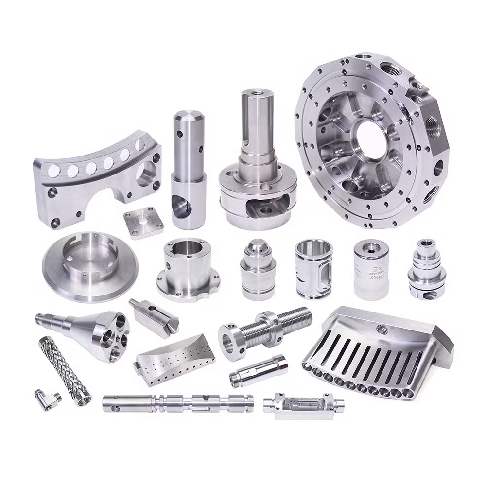
If the end part has to hold ±0.005 mm or take structural load, print it for fit and machine the final in aluminum or steel. We run both processes, so we can tell you which one the geometry actually needs.
Common questions
How accurate does a scan need to be for a printed part?
Match the scanner to the print tolerance, not the other way around. Most resin and filament processes hold ±0.1 mm at best, so a scan at ±0.02–0.05 mm is already tighter than the printer.
Paying for higher scan accuracy only helps if you plan to machine the final part from the same data.
Can you scan a part and print it without a CAD model?
Yes, for fit and form checks. A watertight mesh can go straight to a slicer.
A mesh is not a parametric model. If you need to change a dimension, add a thread, or hold a tolerance, someone has to rebuild that feature in CAD.
What surfaces cause scan problems?
Clear, mirrored, and black matte finishes. Each one either passes light through or scatters it away from the sensor.
A light dusting coat can help, but it adds thickness. For critical dimensions, measure the coating first or use a contact method instead.
Do I need CT scanning for internal features?
Only when the feature is hidden from every angle. A cross-drilled hole can often be scanned from both ends. A closed cooling channel cannot.
CT is slower and costs more, so it is usually reserved for castings and additive parts with internal lattice or channels.
Can the same data be used for CNC machining?
Yes, and this is where scan data often pays off twice. The mesh is used to print a fit sample, then rebuilt as a solid model for 5-axis machining.
We quote both routes from one upload, so you can compare a printed prototype against a machined production part.
What file formats do you accept?
STL, OBJ, PLY, and STEP are all workable. Point clouds are fine as a starting point, but a meshed file saves cleanup time.
Send the original scan if you have it. We would rather trim the data ourselves than work from a simplified export.
Send a scan or a broken part
Upload the file or a few photos. You get a quotation and a free DFM analysis within 12 hours, and we will tell you if printing is the right route.
12-hour quote100% inspectionNDA on request









