Tool nose radius compensation for turning tools is a common problem in CNC turning processing. This paper analyzes the impact of tool nose radius and presents the tool nose radius compensation methods based on CNC systems with different functions.
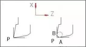
When programming a CNC lathe machining program, the tip of the turning tool is theoretically considered a point. Point P, as shown in Figure 1a, is the tip of the theoretical tool. However, in order to increase the tool life and reduce the roughness of the workpiece surface, the tool tip is usually ground into an arc with a small radius (usually the arc radius R is between 0.4 and 1.6), as shown in Figure 1b in the X direction and the intersection point P in the Z direction is called the tip of the imaginary tool. This point is the point that determines the machining path during programming, and the CNC system controls the movement path of this point. However, the cutting edges that work during the actual cutting are the tangent points A and B of the arc, which are the points that form the surface of the workpiece during the actual cutting. Obviously, the imaginary tool tip point P is different from the actual cutting points A and B. Therefore, if the tool tip fillet radius is not compensated during CNC machining or CNC programming and only the program is programmed according to the contour of the part, it will inevitably produce processing errors.
Figure 1 Imaginary tip of a round-nosed knife
1. Trajectory analysis and calculation of imaginary tool tip offset value
When turning with a round-nose turning tool, the actual cutting points A and B determine the machining dimensions in the X and Z directions, respectively. As shown in Figure 2, when turning a cylindrical surface or of an end face (their generatrix is parallel to the coordinate axis Z or (or

Figure 2 Influence of tool nose arc radius
1. Error analysis and offset value calculation for machining tapered surfaces
As shown in Figure 3a, the imaginary point of the tool tip P moves along the contour of the workpiece CD. If it is programmed according to the CD contour line and the actual cutting is performed with a fillet turning tool, a residual error of CDD1C1 will inevitably occur. Therefore, during actual processing, the actual cutting point of the round nose turning tool should be moved to the contour line CD and along CD, as shown in Figure 3b, so as to eliminate the height residual. At this time, the trajectory C2D2 of the imaginary tool tip and the contour line CD differ by ΔX in the X direction and by ΔZ in the Z direction. Assuming that the tool radius is r, we can find :
![]()

Figure 3 Round head turning tool processing a conical surface
2. Error analysis and offset value calculation for arc surface processing
Processing arcuate surfaces with round-nose turning tools is fundamentally similar to processing conical surfaces. As shown in Figure 4, a 1/4 convex-concave arc is processed. CD is the contour of the part, point O is the center of the circle and the radius is R. The cutting points of the tool as well as the start and end point. The arc contour points are C and D respectively, and the corresponding imaginary tool tip is C1 and D1.
For processing the convex arc shown in Figure 4a, the arc C1D1 is the imaginary trajectory of the tool tip, the point O1 is the center of the circle, and the radius is (R+r) for processing of the concave arc illustrated in Figure 4b, the arc C2D2; is the imaginary tool. The center of the circle is point O2 and the radius is (Rr). If you program according to the imaginary path of the tool nose, you must program with the relevant arc parameters C1D1 or C2D2 (dashed line), as shown in the figure.

Figure 4: Round head turning tool processing a 90° convex and concave arc
2. Tool nose corner radius compensation method
Modern CNC systems usually have tool corner radius compensators with tool tip arc radius compensation functions (i.e. G41 left compensation and G42 right compensation functions) . For this type of CNC lathe, programmers can program directly based on the shape of the workpiece outline. take the tool radius into account when programming The radius is zero. Before CNC machining, the tool arc radius value must be input into the corresponding tool compensation number on the CNC machine tool. During the machining process, the CNC system automatically calculates the imaginary path of the tool tip according to the machining program and. The arc radius of the tool and performs tool radius compensation to complete workpiece processing. When the tool radius changes, there is no need to modify the machining program. You just need to change the tool arc radius value of the compensation number of the corresponding tool number. It should be noted that for some CNC systems with G41 and G42 functions, in addition to entering the radius of the tool tip fillet, the position of the imaginary tool tip relative to the tool center round-nosed must also be entered. internal and external turning tools or left, the tool tip position of the right offset knife is different.
When the CNC system of a CNC lathe has a tool length compensator, the programming is directly based on the shape of the workpiece contour. Before processing, enter the above ΔX and ΔZ values into the tool length compensator of the machine tool and call. the compensation number of the corresponding tool during processing.
For some economical CNC systems that do not have a compensation function, programming can be done directly based on the imaginary tool tip path, that is, the tip path of the The imaginary tool is given during programming, such as the dotted trajectory shown. in Figures 3b and 4. If the calculation using manual programming is quite complicated, you can usually use computer drawing software (such as AutoCAD, CAXA electronic drawing board, etc.) to first draw the outline of the workpiece, then draw the corresponding imaginary trajectory of the tool tip according to the fillet radius of the tool tip and find out the relevant points through the software coordinates for programming; for more complex parts, computer-aided programming (CAM) can also be used, for example using C; When programming the AXA CNC lathe software, there are two ways to compensate for the tool tip radius: taking into account the radius compensation during programming and the radius compensation by the machine tool . For some CNC systems that do not have a compensation function, radius compensation must be taken into account when programming. programming According to the given tool, the tip radius and workpiece contour will automatically calculate the imaginary tool tip path, and the processing program for the imaginary tool tip path will be generated by software post-processing. For this type of CNC system, when the tool tip radius changes due to tool wear, resharpening or replacing new tools, it is necessary to recalculate the imaginary tip path of the tool and modify the machining program, which is complex, tedious and difficult to execute. ensure the accuracy of processing.
From the above analysis of the influence of the turning tool tip radius on the workpiece, it can be seen that in order to ensure the accuracy of workpiece processing, compensation of the turning tool tip radius Turning should be performed in CNC machining, especially finish machining. Since the functions of current CNC systems are unequal, different methods are adopted in practical applications for different types of CNC systems. Some need to take radius compensation into account when programming, and others can perform radius compensation in machine tools.
Daguang focuses on providing solutions such as precision CNC machining services (3-axis, 4-axis, 5-axis machining), CNC milling, 3D printing and rapid prototyping services.


