3+2 machining is a technology that uses the two axes of rotation of a five-axis machine-tool to lock the three-axis milling program in the inclined position, hence the name “machining 3+2”.
It is also called “five -axis positioning machining” because during the machining process, the fourth and fifth axes are used to position the tool to a fixed position instead of manipulating the tool continuously. This clearly distinguishes machining 3+2 from simultaneous machining over five axes. Other names that appear, depending on the characteristic angle of the tool, are inclined machining, fixed machining and inclined machining.
The main advantage of 3+2 machining is that it allows the use of shorter and more rigid tools than machining three traditional axes. In case 3+2, the pin can be lowered closer to the room and the tool can be tilted to the surface. In turn, the use of shorter tools allows faster advances in advance and less deviation from the tool. This means a good surface finish and more precise dimensional results with reduced cycle times. In addition, other advantages include shorter tool movements, less program lines and less configuration of equipment.
This technology is becoming more and more popular in molding workshops because it solves the problem of deep holes in complex molds which otherwise only be machined using fine or elongated tools. Long and fine tools increase the risk of deviation or grazing, and tool extensions can create issues of clearance. Machining in 3+2 also allows direct machining of vertical mold nuclei in the experiences and steep walls. This strategy can reduce or eliminate electroerosion machining operations (EDM).
The meaning of the five axes
The “5” in five -axis machining refers to the number of directions in which the tool can be oriented when it approaches the surface of the room. A significant advantage of the 5 -axis system is the possibility of treating five sides of a part in a single configuration. All areas are accessible except the side placed on the table.
Often, the process on a three -axis VMC requires turning the part or rolling from one montage to another to access all sides of the room. But unfortunately, each time an operator must open the VMC door to return or rotate a room, or load or unload a room, remove shavings or make a quality inspection during the process, the spindle must be stopped. This means that a piece requiring machining on six sides may have to be moved by the operator seven times (loaded, repositioned five times and discharged). Machining on five faces eliminates these additional downtime.
Of course, applications are not limited to the treatment of molds. The shapes of bent or tilted tubes in the room, such as the orifices of a cylinder head or the pipes of a valve body, can often be machined effectively in 3+2 if the FAO software supports this application. In addition, 3+2 can help make certain types of parts from a solid body rather than from a complex molded room. Prototyping work also benefits from this technology.
Holes drilling from several angles with a single device is also an important advantage of 3+2 machining. The alignment of the forest in the right direction is done in programming rather than in workshop with multiple settings and complicated fixings.
Reflection strategy on three axes of machining 3+2
One way to consider machining 3+2 is to view the characteristics of the part selected on a three -axis VMC. If the difficult characteristics are on a practical work plan, an effective three axis machining can be carried out. In some cases, the part can be positioned on a special support or a sinusoidal plate so that it is oriented in the right direction for machining with three axes. However, 3+2 uses the angle of the fixed position of the tool to create the same relative meaning; alignment. This is accomplished by creating a virtual work plan which locates the characteristics of the part so that the angle tool performing the program with three axes has the desired effect. CAM software performs all the transformations in the coordinate system to produce these results.
The advantage of machining 3+2 is that work plans for several machining areas can be established on the same room. Wherever 3+2 is advantageous and practical, users can select these areas without enjoying the part. An example would be the machining of the chassis on the opposite sides of the cavity.
3+2 machining operations can be carried out continuously, with the reset tool at the appropriate operating angle. (Consequently, in certain cases, this technique is called “indexing machining”.) One of the disadvantages of indexing is that the mixture between the surfaces created from different tool angles must be carefully verified to guarantee that The desired effect is produced. The mixing problem seems to be a function of the programming software and its level of development.
CAM software is suitable for machining 3+2
Many FAO software suppliers have developed special tools to create tool paths for 3+2 machining. Not all 5 -axis programming software does not offer this technology. Like all the features of software, ease of use and efficiency of machining tools 3+2 vary from one software to the other.
A supplier specializing in mold manufacturing software can offer machining 3+2 as a characteristic of its 5 -axis machining products. Since there is no standard terminology to describe this technology, this functionality can be neglected when examining the functionality of CAM software. In one case, the functionality was listed as part of a machining strategies library, where it was described as “tilt on five deep pocket axes with short tools”.
Potential users of machining 3+2 must assess the avoidance capacities of collisions and program simulation of the FAO software that they consider. The capacities of machining 3+2 also vary depending on the level of automation to facilitate the programming functions. Establish the work plan and the machining area; The limits of false round for the movement of the cutting tool and, depending on the system, certain stages of control of the angle of the tool may be more or less automated. The automatic definition of feeding and retraction between treatment areas is a functionality of certain systems.
Almost all of cam software suppliers that offer 3+2 machining for five -axis machines highlight the importance of effective collision prevention. Even if machining 3+2 simplifies the movement of the tool because it is essentially a machining on three axes without spindle head “torsion” to maneuver the tool, it is not without risks.
In general, programming 3+2 is not a brake. In fact, the powerful functions of the tools programmed in 3+2 machining are one of the main reasons why this technology has become popular.
Machining 3+2 is a complement to complete machining at five axes
Machining 3+2 is a very practical technology and is one of the options that make 5 -axis machining centers a precious asset. But he will never be able to replace simultaneous machining on five axes. For example, five axes are necessary simultaneously to create lively angles in a cavity using a strawberry on the flat end. Machining 3+2 generally uses ball bearing strawberries, as is machining three axes on a machining center three traditional axes. Other cutting modes using conical tools, pacifier or other special geometry tools may require complete movement on five axes to optimize the final result.
In some cases, we recommend a 3+2 machining for the draft, followed by simultaneous machining on five axes for the finish. For the draft, the shorter tool length authorized by the 3+2 makes it suitable for high -speed cutting techniques. In many cases, a 3+2 can be made effectively for rest (go back with the smallest tool and “clean” the material left by the brutal operation with the largest tool).
For some companies, machining 3+2 simplifies the Transition of strawberry three axes to simultaneous machining five axes. Fracking with fixed tools positions provides a positive experience for machining at five axes. As a software publisher pointed out, continuously switching from a fixed tool position to another is only a step of simultaneous machining on five axes.
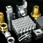
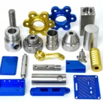
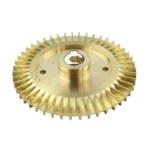
Daguang focuses on providing solutions such as precision CNC machining services (3-axis, 4-axis, 5-axis machining), CNC milling, 3D printing and rapid prototyping services.