When titanium alloy encounters thin-walled parts, it seems that the difficulty of processing 2mm thin-walled materials is doubled. However, after detailed analysis, there are still corresponding solutions:
Analysis of titanium alloy thin-walled cavity parts
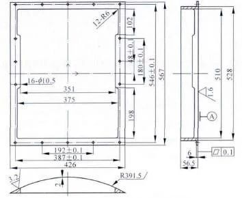
1.1 Part size analysis
The minimum size of the rectangular outline of the cover part of the envelope is 567 mm x 426 mm x 56.5 mm. The overall appearance is a large arcuate thin-walled cavity structure. The wall thickness of the arc surface cavity is 2mm, and the thickness of the connecting shoulder at both ends is 6mm. . In order to ensure the seal between the cover and the case after installation, the flatness of the installation surface of the cover parts should be 0.1mm.
Figure 1
1.2 Analysis of processing technology
The key part of the processing of the cover part is the cavity. The difficulty is to solve the chattering problem of the cover part during processing due to its thin-walled structural characteristics. The overall structure is simple. The cover plate and the mounting surface of the housing have high requirements for flatness and surface quality. The requirements for dimensional accuracy and surface quality of the remaining parts are not high. All processing procedures can be carried out on a CNC machining center.
A blank sheet of 570mm x 430mm x 60mm is used here. The processing of titanium alloy thin-walled cavity cover parts requires three processing steps: ① Rough milling and fine milling of the convex cavity, that is, the processing of the installation hole; cavity; ③ Installation surface finishing treatment.
Processing technology and tooling scheme design
2.1 Rough milling, fine milling and processing of convex cavity mounting holes
The external dimensions of the processed roofing pieces are 567 mm ± 0.1 mm x 426 mm ± 0.1 mm x 57 mm. Ensure that the roughness of all treated surfaces is Ra3.2 Um. Leave a machining allowance of 0.5 mm in the thickness direction and process 4 M16 parts deep on one surface. manufacturing of large planes. These are the fixing holes for the convex cavity machining process. The four threaded holes are based on the symmetrical center point of the large plane, and the positioning size corresponds to the fixing holes of the 6061 aluminum-magnesium alloy tooling fixed on the workbench, so that the cover part adopts “a side “. The two-pin positioning method uses screw clamping to achieve positioning and tightening.

Figure 2 Rough machining
Secondly, process the convex cavity of the cover part and the surfaces of the installation steps on both sides. For roughing machining of the convex cavity and roughing and finishing machining of the surfaces of the installation steps on both sides, a four-edged end mill with high cobalt content is selected, and the Parallel milling curved surface roughing machining method is selected, as shown in Figure 2. During the cutting process, high-speed tool steel tools should maintain sufficient cutting fluid to extend the working life. life of the tool.
Then, a polycrystalline cubic boron nitride spherical milling cutter is used for finishing the convex cavity, and the simplified surface finishing method is selected as shown in Figure 3. The overall error is controlled within 0.012mm. Finally, process the 16 mounting holes on the mounting surface (all are threaded connection holes) and use a 0.5mm carbide drill bit to drill directly to meet the processing requirements. After this process, the burrs should be removed, the sharp edges should be blunted, and the surface of the convex cavity should be polished without obvious knife marks to avoid affecting the positioning and clamping of the next process.

Figure 3 Convex part cavity finishing simulation
2.2 Rough and fine cavity milling and milling tooling
Figure 4 shows the milling tooling for rough and fine milling of the concave cavity. The tooling fixed on the workbench in the previous process is made into a concave curved surface to match the convex cavity of the cover part. Both sides of the tooling match the surfaces of the installation steps at both ends of the cover part to achieve precise positioning. The places where the concave curved surface of the tooling intersects the flat surface and the flat surface are cleaned to avoid burrs or sharp edges that affect positioning accuracy. Then use the 10 M10 threaded holes on either side of the tooling to finalize the tightening and fixing of the cover parts and tooling.
Grooving is used for rough machining of the concave cavity of roofing parts. The cutting tools, cutting fluid and cutting parameters are basically the same as those of the convex cavity. The four M16 clamping holes in the previous process can easily cause vibration and damage the tool during the milling process, so you need to be careful during cutting. The milling tools and parameters are the same as for finishing convex pockets.

Figure 4
Things to note during processing are:
① Natural failure treatment should be provided between the rough machining and finish machining of the concave cavity of the cover part to completely release the internal stress generated by the cutting process and prevent processing deformation;
② When finishing and tightening, the contact surfaces of the cover parts and tooling should be exchanged several times, and the black grinding marks on all contact surfaces of the tooling should be repaired several times to ensure that there is no obvious gap between the positioned cover. the parts and the contact surface of the tooling;
③ Clean up the chips at the root and corners as well as the contact surfaces in the tooling to avoid crushing the cover parts and affecting the surface quality; ④ When tightening the screws on both sides, they should be rotated symmetrically from left to right to avoid damage caused by tightening force.
2.3 Finishing the mounting surface
After inspecting the processed mounting surface, the main reasons for excessive surface flatness and roughness are factors such as tool marks or processing deformation, which require refinishing of the mounting surface.

Figure 5
The positioning reference and the clamping fixed surface should select the parallel mounting surfaces on both sides of the cover part, first choose the precision milling processing method, and then choose the fine grinding processing method, and finally choose the grinding processing method, and. continuously detect during the treatment process. Reserve a machining allowance of less than 0.5mm during the convex cavity machining process to meet the precision requirements. Cover parts that have passed inspection after processing.
TC4 titanium alloy is a difficult material to machine, and the cover parts have a wall and cavity structure. The same tooling is used in actual CNC machining, and the design can be technically consistent with the overall process of the cover parts; not only solves the assembly problem. The positioning of the clamp can also intelligently overcome vibration when processing 2mm thin walls, avoiding problems such as excessive clamping force and deformation. In processing practice, the rational use of tooling can reduce costs, facilitate operation and save time and efficiency.
Daguang focuses on providing solutions such as precision CNC machining services (3-axis, 4-axis, 5-axis machining), CNC milling, 3D printing and rapid prototyping services.


