1. Tower
A lathe is a machine tool that primarily uses turning tools to turn rotating parts. Drills, reamers, reamers, taps, dies and knurling tools can also be used on lathes for corresponding processing. Lathes are mainly used for processing shafts, discs, sleeves and other parts with rotating surfaces. They are the most widely used type of machine tools in machine manufacturing and repair plants.
1. The old “bow tower” with pulleys and bow rods
As early as ancient Egyptian times, people had invented the technology of turning wood with tools while rotating it around its central axis. At first, people used two standing trees as supports to install the wood to turn, used the elasticity of the branches to wrap the rope on the wood, pulled the rope with hand or foot to turn the wood, and held the knife to turn it. cut.
This ancient method gradually evolved by wrapping a rope around a pulley two or three times. The rope was placed on an elastic rod bent into the shape of an arc. The arc was pushed and pulled back and forth to rotate the object being treated. It was the “bow trick”.
2. The medieval “pedal tower” with crankshaft and flywheel transmission
In the Middle Ages, someone designed a “pedal lathe” that used a pedal to turn the crankshaft and drive the flywheel, which was then transmitted to the spindle to turn. In the mid-16th century, a French designer named Besson designed a lathe for turning screws using a screw bar to slide the tool. Unfortunately, this trick was not popularized.
3. In the 18th century, bedside boxes and chucks were born
In the 18th century, someone else designed a lathe using a pedal and connecting rod to turn the crankshaft, which could store rotational kinetic energy on the flywheel. It also went from direct room rotation to a rotating bedside box. to hold the workpieces.
4. In 1797, the Englishman Maudsley invented the epoch-making tool lathe.
This lathe features a precision lead screw and interchangeable gears.
Maudsley was born in 1771. At the age of 18, he was the right-hand man of the inventor Brammer. It is said that Bramer had always worked on the farm. At the age of 16, an accident left him with an injury to his right ankle, forcing him to turn to woodworking with limited mobility. His first invention was the flush toilet in 1778. Maudsley began helping Brammer design hydraulic presses and other machines. He only left Brammer at the age of 26 because Bramer abruptly rejected Maurizio’s proposal for a salary increase above 30 shillings. per week.
The year Maudsley left Bramer, he made the first threading lathe, an all-metal lathe with a tool base and tailstock that could move along two parallel guide rails. The guide surface of the guide rail is triangular, and when the spindle rotates, it drives the screw to move the tool holder sideways. This is the main mechanism of modern towers. With this lathe, precision metal screws of any pitch can be turned.
Three years later, Maudsley built a more complete lathe in his own workshop, with interchangeable gears capable of changing the feed rate and pitch of the thread being machined. In 1817, another Englishman, Roberts, used a four-stage pulley and back pulley mechanism to change the rotational speed of the spindle. Soon, larger towers also appeared, making a great contribution to the invention of steam engines and other machines.
5. The birth of various special lathes to improve the degree of mechanization and automation
In 1845, the American Fitch invented the turret lathe; in 1848, turn-taking appeared in the United States; In 1873, the American Spencer made a single-axis automatic lathe, and soon he made a three-axis automatic lathe. round; 20 At the beginning of the century, towers equipped with gearboxes driven by separate motors appeared. Through the invention of high-speed tool steel and the application of electric motors, lathes have been continuously improved and finally reached the modern level of high speed and high precision.
After World War I, various high-efficiency automatic lathes and specialized lathes developed rapidly due to the needs of the arms, automobile and other machinery industries. In order to improve the productivity of small batches of parts, lathes equipped with hydraulic profiling devices were popularized in the late 1940s. At the same time, multi-tool lathes were also developed. In the mid-1950s, program-controlled lathes, equipped with punch cards, lock plates, dials, etc., were developed. CNC technology began to be used in lathes in the 1960s and developed rapidly after the 1970s.
6. Towers are divided into several types according to their uses and functions.
Ordinary lathes have a wide range of processing objects, a wide adjustment range of spindle speed and feed, and can process internal and external surfaces, end faces and threads internal and external of the room. This type of lathe is mainly manually operated by workers and has low production efficiency. It is suitable for single part and small batch production and repair workshops.
Turret lathes and rotary lathes have a turret tool holder or rotating tool holder that can hold multiple tools. Workers can use different tools to complete multiple processes in one workpiece clamping and are suitable for batch production.
Automatic lathes can automatically carry out multi-process processing of small and medium-sized parts according to certain procedures. They can automatically load and unload materials and repeatedly process a batch of the same parts. They are suitable for mass and serial production.
Multi-tool semi-automatic lathes are divided into single-axis, multi-axis, horizontal and vertical types. The layout of the single-axis horizontal lathe is similar to that of an ordinary lathe, but two sets of tool holders are installed at the front, rear or top and bottom of the spindle. They are used to process discs, bushings and shaft parts. Its productivity is 3 to 5 times higher than that of ordinary lathes.
The profiling lathe can imitate the shape and size of a model or prototype and automatically complete the part processing cycle. It is suitable for small batch and batch production of parts with complex shapes, and its productivity is 10-15 times that of. ordinary turns. There are several tool holders, multi-axis, chuck type, vertical type and other types.
The spindle of a vertical lathe is perpendicular to the horizontal plane, the workpiece is clamped on a horizontal rotary table, and the tool holder moves on the beam or column. It is suitable for processing larger and heavier parts, which are difficult to fit on ordinary lathes. It is generally divided into two categories: single column and double column.
While the excavator tooth lathe rotates, the tool holder periodically reciprocates radially, which is used to form the tooth surfaces of forklift cutters, hobs, etc. Usually, with a relief grinding attachment, a small grinding wheel driven by a separate electric motor relieves the tooth surface.
Specialty lathes are lathes used to process specific surfaces of certain types of parts, such as crankshaft lathes, camshaft lathes, wheel lathes, axle lathes, roller lathes, and roller lathes. ingots.
The combination lathe is mainly used for turning, but with the addition of some special parts and accessories, it can also be used for boring, milling, drilling, inserting, grinding and other processing. It has the characteristics of a “machine with many”. functions” and is suitable for engineering vehicles, ships or mobile applications. Repair work at the repair station.
2. Boring machine
Although the factory cottage industry is relatively backward, it has trained and trained many technicians, although they are not experts in machine manufacturing, but they can make various hand tools, such as knives, saws, etc. Needles, drills, cones, grinders, arbors. , sleeves, gears, bed frames, etc. In fact, the machine is assembled from these parts.
1. The first designer of boring machines – boring machine Leonardo da Vinci is called the “Mother of machines”
Speaking of boring machines, we must first talk about Leonardo da Vinci. This legendary figure may have been the designer of the first boring machine used for metal processing. The boring machine he designed was powered by water or a pedal. The boring tool rotated near the workpiece and the workpiece was fixed on a movable table driven by a crane. In 1540, another painter painted a painting of “The Art of Pyrotechnics” with the same image of a boring machine. The boring machine of the time was specifically used for finishing hollow castings.
2. The first boring machine born for processing cannon barrels (Wilkinson, 1775)
In the 17th century, due to military needs, the cannon manufacturing industry developed rapidly. The manufacture of cannons became a major problem that urgently needed to be resolved.
The world’s first true boring machine was invented by Wilkinson in 1775. Actually, to be precise, Wilkinson’s boring machine was a drilling machine capable of precisely machining cannons. It was a hollow cylindrical boring bar with both ends mounted on bearings.
Wilkinson was born in the United States in 1728. At the age of 20 he moved to Staffordshire and built Bilston’s first iron furnace. For this reason, Wilkinson was known as the “Master Blacksmith of Staffordshire”. In 1775, Wilkinson, 47, worked hard in his father’s factory and eventually created a new machine capable of drilling cannon barrels with rare precision. Interestingly, after Wilkinson’s death in 1808, he was buried in a cast iron coffin designed by himself.
3. Boring machines made an important contribution to Watt’s steam engine
Without the steam engine, the first wave of the industrial revolution would not have been possible. As for the development and application of the steam engine itself, in addition to the necessary social opportunities, certain technical conditions cannot be ignored, because the manufacture of steam engine parts is not as simple as a carpenter cutting wood. This requires special manufacturing. metal parts. The requirements for form and processing precision are very high, which cannot be achieved without the corresponding technical equipment. For example, when manufacturing steam engine cylinders and pistons, the accuracy of the outer diameter required in the piston manufacturing process can be measured from the outside during cutting. However, to meet the accuracy requirements of the cylinder inner diameter, it is necessary to measure the required outer diameter accuracy in the piston manufacturing process. not easy to achieve this using general treatment methods.
Smeaton was the best mechanical technician of the 18th century. Smeaton designed 43 pieces of waterwheel and wind turbine equipment. When making a steam engine, the most difficult thing for Smeaton was to process the cylinder. It is quite difficult to turn the inner circle of a large cylinder into a circle. To this end, Smeaton built a special machine tool for cutting the inner circle of the cylinder at Karen Iron Works. This type of waterwheel driven boring machine has a cutter installed at the front end of its long spindle. This cutter can rotate in the cylinder, so that its inner circle can be machined. Since the tool is installed at the front end of the long shaft, problems such as shaft deflection will occur. Therefore, it is very difficult to machine a truly round cylinder. To this end, Smeaton had to change the position of the cylinder several times for the treatment.
To solve this problem, the boring machine invented by Wilkinson in 1774 played an important role. This type of boring machine uses a water wheel to rotate the cylinder of material and push it toward the center-mounted tool. Due to the relative movement between the tool and the material, the material is drilled into a cylindrical hole with high precision. At that time boring machines were used to make cylinders with a diameter of 72 inches, and the error was no greater than the thickness of a sixpence piece. Measured by modern technology, this is a big mistake, but in the conditions of that time it was already very difficult to achieve this level.
However, Wilkinson’s invention was not applied for patent protection and people copied and installed it. In 1802, Watt also wrote about Wilkinson’s invention in his book and copied it at his steelworks in Soho. Watt later also used Wilkinson’s magic machine to make cylinders and pistons for steam engines. It turns out that for the piston you can measure the dimension on the outside and cut it at the same time, but for the cylinder it is not so simple and you have to use a boring machine. At this time, Watt used a water wheel to rotate the metal cylinder and push the tool attached to the center forward to cut the inside of the cylinder. As a result, the error of the 75-inch diameter cylinder was less than the thickness of a coin. , which was at that time very advanced.
4. The birth of the table boring machine (Hutton, 1885) in the following decades
Many improvements were made to Wilkinson’s boring machine. In 1885, Hutton in the United Kingdom manufactured a lifting boring machine, which became the prototype for modern boring machines.
3. Milling machine
In the 19th century, the British invented boring machines and planers to meet the needs of the industrial revolution such as steam engines, while the Americans focused on the invention of milling machines to produce large numbers of weapons. A milling machine is a machine equipped with cutters of different shapes, which can cut workpieces with special shapes, such as spiral grooves, gear shapes, etc.
As early as 1664, the British scientist Hooke used a rotating circular tool to create a cutting machine. This could be considered a primitive milling machine, but society at the time did not welcome it with enthusiasm. In the 1840s, Pratt designed the so-called Lincoln milling machine. Of course, it was the American Whitney who truly established the status of milling machines in machine manufacturing.
1. The first ordinary milling machine (Whitney, 1818) 1818
Whitney built the world’s first ordinary milling machine, but the patent for the milling machine was first “obtained” by the British Bodmer (the inventor of the gantry planer with knife feeder) in 1839. Since the cost of milling machines was too high, few people were interested in them at the time.
2. The first universal milling machine (Brown, 1862) After a period of silence, the milling machine
Active again in the United States. On the other hand, it cannot be said that Whitney and Pratt laid the foundations for the invention and application of milling machines. The real credit for the invention of milling machines that could be used in various factory operations should belong to American engineer Joseph Brown.
In 1862, the American Brown manufactured the world’s first universal milling machine. This milling machine was a historic initiative by being equipped with a universal indexing plate and an integrated milling cutter. The worktable of the universal milling machine can rotate at a certain angle in the horizontal direction and is equipped with accessories such as an end mill head. The “Universal Milling Machine” he designed was a great success when it was exhibited at the Paris World’s Fair in 1867. At the same time, Brown also designed a shaped milling cutter that would not deform after grinding , then made a grinding machine for milling cutters, bringing the milling machine to its current level.
4. Planer
In the process of invention, many things are often complementary and intertwined: to make a steam engine, the help of a boring machine is necessary; after the invention of the steam engine, the gantry planer was again called upon in terms of process; requirements. It can be said that it was the invention of the steam engine that led to the design and development of “working machines”, from boring mills and lathes to gantry planers. Basically, a planer is a “plane” used for planning metal.
1. Gantry planer for processing large flat surfaces (1839) due to the need to process flat surfaces of steam engine valve seats
Since the early 19th century, many technicians have begun research in this area, including Richard Robert, Richard Pratt, James Fox, and Joseph Clement. They started in 1814 and within 25 years were independently manufacturing gantry planers. This type of gantry planer clamps the workpiece on the reciprocating platform and the planer cuts one side of the workpiece. However, this type of planer does not yet have a knife feeding device and is in the process of transforming from a “tool” to a “machine”. In 1839, a British man named Bodmer finally designed a gantry planer with a knife feed device.
2. A ball head planer for processing small aircraft. Another Briton, Nesmith, invented and manufactured a ball head planer for processing small aircraft within 40 years from 1831.
It can fix the object to be processed on the bed while the tool moves back and forth.
Since then, with the improvement of tools and the emergence of electric motors, gantry planers have developed in the direction of high-speed cutting and high precision on the one hand, and in the direction of the large scale on the other hand.
5. Grinder
Grinding is an ancient technology that humans have known since ancient times, this technology was used to grind stone tools. Later, with the use of metal utensils, the development of grinding technology was promoted. However, the design of grinding machines worthy of the name is still a modern thing. Even in the early 19th century, people still ground by spinning natural millstones and letting them come into contact with the workpiece.
1. The first grinding machine (1864) In 1864, the United States manufactured the world’s first grinding machine
This is a device that installs a grinding wheel on the sliding tool holder of a lathe and gives it an automatic transmission. Twelve years later, Brown in the United States invented a universal grinder close to a modern grinder.
2. Artificial grindstones – the birth of the grindstone (1892) and the demand for artificial grindstones also increased.
How to develop a grinding wheel more resistant to wear than the natural grinding wheel? In 1892, American Acheson successfully produced silicon carbide based on coke and sand, which was an artificial grinding wheel called abrasive C; two years later, an abrasive with alumina as the main component was successfully produced. the crusher was more widely used.
Later, through further improvements in bearings and guide rails, the precision of grinders became higher and higher, and they developed in a professional direction. Internal grinders, surface grinders, roller grinders, gear grinders and universal grinders appeared.
6. Drill
1. The drilling technology of the ancient drilling machine “gong pulley” has a long history. Archaeologists have discovered that humans invented devices for drilling holes in 4000 BC. The ancients would install a beam on two vertical columns, hang a rotating punch down the beam, then use a bowstring to wind the punch so that it rotated, so that holes could be drilled in the wood and the stones. Soon, people also designed a punch tool called a “window”, which also used elastic bowstrings to rotate the punch.
2. The first drill (Whitworth, 1862) Around 1850, the German Martignoni manufactured for the first time a twist drill for drilling metals; In 1862, at the International Exhibition held in London, England, Englishman Whitworth exhibited a motor-driven cast iron cabinet frame. drill, which became the prototype of the modern drill.
Since then, various drilling machines have appeared one after another, including radial drilling machines, drilling machines equipped with automatic feed mechanisms, and multi-axis drilling machines capable of drilling multiple holes at the same time. With improvements in tool materials and drill bits, as well as the use of electric motors, large, high-performance drills were eventually manufactured.
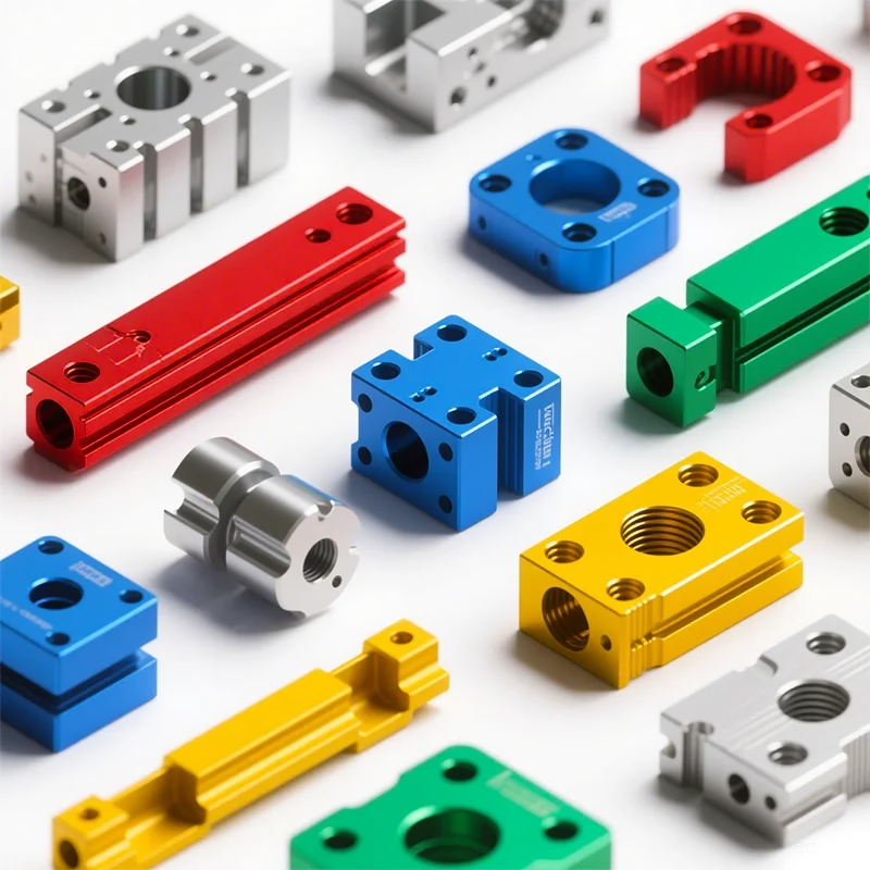
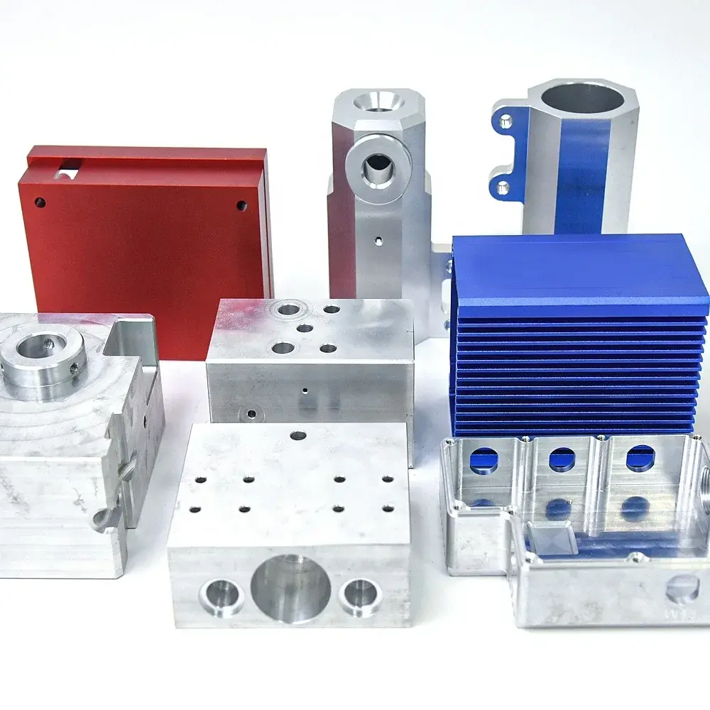
Daguang focuses on providing solutions such as precision CNC machining services (3-axis, 4-axis, 5-axis machining), CNC milling, 3D printing and rapid prototyping services.


