During the machining process, many shaft parts have an aspect ratio of L/d>25. Under the action of cutting force, gravity and tip clamping force, the horizontal thin shaft can easily bend or even become unstable. Therefore, the stress problem of the thin shaft needs to be improved when rotating the thin shaft.
Processing method: Use reverse feed turning, and adopt a series of effective measures such as reasonable tool geometric parameters, cutting quantity, tensioning device and sleeve-type tool holder.
Analysis of factors causing bending deformation during turning of thin shafts
There are two main traditional clamping methods used for turning thin shafts on lathes: one is: clamp installation and top installation; the other method is: two central installations. Here we mainly analyze the method of clamping a clamp and a top. As shown in Figure 1.
Figure 1 One-clamp, one-top clamping method and stress analysis
Through the actual processing analysis, the main reasons for the bending deformation of thin shaft caused by turning are:
(1) Cutting force causes deformation
During the turning process, the generated cutting force can be decomposed into axial cutting force PX, radial cutting force PY and tangential cutting force PZ. Different cutting forces have different effects on the bending deformation produced when rotating a thin shaft.
1) Influence of the radial cutting force PY
The radial cutting force acts vertically on the horizontal plane passing through the axis of the thin shaft. Due to the low rigidity of the thin shaft, the radial force will bend the thin shaft, causing it to bend and deform in the horizontal plane. direction The influence of cutting force on the bending deformation of the thin shaft is shown in Figure 1.
2) Influence of the axial cutting force PX
The axial cutting force acts parallel to the axis of the elongated shaft and forms a bending moment on the workpiece. For general turning processing, the impact of axial cutting force on the bending deformation of the workpiece is not significant and can be ignored. However, due to the low rigidity of the thin shaft, its stability is also poor. When the axial cutting force exceeds a certain value, the thin shaft will be bent and longitudinal bending deformation will occur. As shown in Figure 2.


Figure 2 Influence of axial cutting force and force analysis
(2) Influence of cutting heat
The cutting heat generated during processing will cause thermal deformation and elongation of the workpiece. Since the tips of the chuck and tailstock are fixed during the turning process, the distance between them is also fixed. In this way, the axial elongation of the thin shaft after being heated is limited, causing the thin shaft to be compressed axially and produce bending deformation.
Therefore, it can be seen that the problem of improving the machining precision of thin shafts is essentially a problem of controlling the stress and thermal deformation of the processing system.
Measures to improve the machining accuracy of thin shafts
In the machining process of thin shaft, in order to improve its machining accuracy, different measures should be taken according to different production conditions to improve the machining accuracy of thin shaft.
(1) Choose the appropriate tightening method
Among the two traditional clamping methods used for turning thin shafts on lathes, double-center clamping is used to accurately position the workpiece and easily ensure coaxiality. However, this method of clamping a thin shaft has low rigidity, significant bending deformation of the thin shaft, and is prone to vibration. Therefore, it is only suitable for installations with low aspect ratio, low machining allowance and high coaxiality requirements. .High artifacts.
When processing thin shafts, the clamping method consisting of a clamp and a top is usually used. However, in this clamping method, if the center is pushed too hard, in addition to bending the thin shaft, it may also hinder the thermal elongation of the thin shaft during turning, causing compression and axial deformation of the thin tree. In addition, the clamping surface of the claw and the center hole may not be coaxial, which will cause overpositioning after clamping, and may also cause the thin shaft to bend and deform, therefore, when l using the one-clamp system. top tightening method, the center should use an elastic center. The thin shaft can be freely extended after being heated to reduce its thermal bending deformation. At the same time, an open metal ring can be inserted between the claw and the thin shaft to reduce the axial contact length between the claw and the thin shaft, eliminating the need for overpositioning during installation to reduce deformation by bending. As shown in Figure 3.


Figure 3 Improved one-grip and collet clamping
(2) Directly reduce force deformation of thin shaft
1) Using the tool holder and center rest
The one-clamp, one-on-top clamping method is used to rotate the thin shaft. In order to reduce the influence of the radial cutting force on the bending deformation of the thin shaft, a tool holder and a rest are traditionally used. equivalent to adding support to the thin shaft, increases the rigidity of the thin shaft, which can effectively reduce the impact of radial cutting force on the thin shaft.
2) Rotation of thin shaft using axial clamping method
Although using a tool holder and center rest can increase the rigidity of the workpiece, it can basically eliminate the influence of radial cutting force on the workpiece. However, it cannot solve the problem of axial cutting force bending the workpiece. Especially for thin shafts with a large length/diameter ratio, this bending deformation is more obvious. Therefore, the axial tightening method can be used to rotate thin shafts. Axial clamping turning refers to the process of rotating a thin shaft. One end of the thin shaft is clamped by a chuck, and the other end is clamped by a specially designed clamping head. The clamp head applies axial tension to the thin shaft. shown in Figure 4.
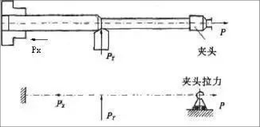

Figure 4 Axial tightening, turning and stress conditions
During the turning process, the thin shaft is always under axial tension, which solves the problem of axial cutting force bending the thin shaft. At the same time, under the action of axial tension, the degree of bending deformation of the thin shaft caused by the radial cutting force is reduced; the axial elongation caused by cutting heat is compensated, and the rigidity and machinability of the thin shaft are improved. . Precision.
3) Turn thin shaft using reverse cutting method
The reverse cutting method means that during the process of turning the thin shaft, the turning tool is advanced from the spindle chuck to the direction of the tailstock, as shown in Figure 5.


Figure 5 Reverse cutting method processing and stress analysis
In this way, the axial cutting force generated during the machining process causes the thin shaft to stretch, thereby eliminating the bending deformation caused by the axial cutting force. At the same time, the use of elastic tailstock tip can effectively compensate for the pressure deformation and thermal elongation of the tool workpiece at the tailstock, and avoid bending deformation of the piece.
The middle slide of the lathe is modified by using double tool turning of the thin shaft, a rear tool holder is added, and two front and rear turning tools are used to turn at the same time, as shown in Figure 6.


Figure 6 Double knife machining and stress analysis
The two turning tools are radially opposed to each other, with the front turning tool installed in the forward direction and the rear turning tool reversed. The radial cutting forces generated by the two turning tools cancel each other out. The workpiece has low stress deformation and vibration, high processing precision, and is suitable for mass production.
4) Turning thin shafts using magnetic cutting method
The principle of magnetic cutting method is basically the same as that of reverse cutting method. During the turning process, the thin shaft is stretched by magnetic force, which can reduce the bending deformation during the machining of the thin shaft and improve the machining precision of the thin shaft.
(3) Reasonably control the cutting quantity
Whether the cutting amount is selected appropriately will affect the amount of cutting force and cutting heat generated during the cutting process. Therefore, the deformation caused when rotating a thin shaft is also different.
1) Cutting depth
Daguang focuses on providing solutions such as precision CNC machining services (3-axis, 4-axis, 5-axis machining), CNC milling, 3D printing and rapid prototyping services.


