In CNC programming, common problems encountered include tool collisions, tool knocks, overcuts, missing processing, redundant processing, too many empty tools, too many lifting tools, and toolpaths. messy tools. This article summarizes these common CNC programming problems. The issue is welcome to forward and collect.
1
Knife collision
Knife collision means that the cutting amount of the tool is too large, and in addition to the cutting edge, the tool holder also hits the workpiece. The main reasons for tool collision are unreasonable adjustment of the safety height or lack of adjustment of the safety height, improper selection of processing methods, improper use of tools and adjustment of the margin for the second draft is smaller than the margin for the first draft. etc. .
1. Excessive knife use
Solution:
Reduce the amount of knives taken. The smaller the tool diameter, the smaller the amount of cutting should be. Under normal circumstances, the cutting quantity of each tool for mold roughing does not exceed 0.5mm, and the cutting quantity for semi-finishing and finishing is even smaller.
2. Choose inappropriate treatment methods

Solution:
Change the contour milling method to the cavity milling method. When the machining allowance is greater than the tool diameter, the contour machining method cannot be selected.
3. Incorrect safety height adjustment

Hit the pliers while lifting the knife
Solution:
(1) The safety height must be higher than the clamping height;
(2) In most cases, the “direct” tool feed and retract method cannot be selected, except for special workpieces.
4. Incorrect setting of secondary coarse aperture margin

Solution:
The margin for the second roughing should be slightly larger than that for the first roughing, usually 0.05 mm larger. If the first roughness allowance is 0.3 mm, the second roughness allowance must be 0.35 mm. Otherwise, the toolbar will easily hit the upper side wall.
Comments:
In addition to the knife collision caused by the above reasons, the cutting tool path sometimes also produces knife collision, so try not to cut the tool path. The most direct consequence of a tool collision is damage to the tool and workpiece and, even more serious, damage to the machine tool spindle.
2
knife
Stabbing refers to a relatively large vibration of the tool due to excessive force. The damage caused by stabbing is that the workpiece will be overcut and the tool will be damaged. When the tool diameter is small and the tool shank is too long or the force is too high, stabbing will occur.
1. The tool diameter is small and the tool holder is too long

The knife is too long and the diameter is too small
Solution:
Use a larger ball cutter to clean up corners or an EDM to machine deep corners.
2. The force is too large (that is, the amount of knife taken is too large)

Solution:
To reduce the cutting quantity (i.e. the overall depth of each cut), when the processing depth is more than 120mm, the cutting tool should be installed twice, i.e. say first install the short tool shaft to process at a depth of 100mm, then install the extended tool shaft to process workpiece less than 100mm and set a small cutting amount.
Comments:
The stabbing phenomenon is more easily ignored by programming beginners, so it should be paid enough attention. When programming, the cutting quantity and maximum processing depth should be determined based on the performance of the cutting material, tool diameter and length, and whether EDM machining is required. for places that are too deep.
3
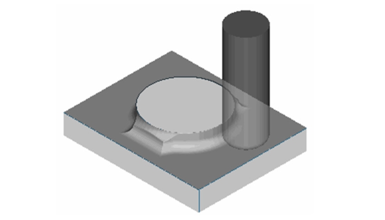
Overcut
Overcutting means the tool cuts parts that cannot be cut, thereby damaging the part. There are many reasons why parts are overcut. The main reasons are low precision of machine tools, tool collision, stabbing, choosing small tools during programming but mistakenly using large tools during actual processing, etc. Additionally, if the machine operator does not adjust the knife precisely, it can cause overcutting.
The situation shown in the image below is an overcut caused by incorrect safety height adjustment.

Overcut
Comments:
When programming you need to be careful. After completing programming, you should check the tool path in detail to avoid overcutting and other phenomena, otherwise the mold will be scrapped or even the machine tool will be damaged.
4
Missing treatment
Missing processing means that there are places in the mold that the tool can process but are not being processed. Among them, the corners of the plane are most likely to be missed, as shown in the figure below.

Lack of machining at the corners of the plan
In order to improve processing efficiency, a larger flat-bottomed knife or round-nosed knife is generally used for a smooth plane. When the corner radius is smaller than the tool radius, a margin will be left at the corner as shown in. the figure below.

Surface milling
In order to clear the margin at the corner, a ball end mill should be used to add additional tool paths to the corner as shown in the figure below.

Additional toolpath
Comments:
Missing machining is one of the most common and easiest problems to ignore. Programmers should be careful not to wait until the mold has been removed from the machine tool to discover the missing machining, which will waste a lot of time.
5
redundant processing
Redundant machining refers to machining areas that cannot be machined by the tool or parts machined by EDM. It mainly occurs in finishing or semi-finishing machining.
Some important parts of the mold or parts that cannot be processed by ordinary CNC machining need to be machined by EDM. Therefore, after roughing or semi-finishing is completed, these parts do not need to be finished with tools, otherwise it will be wasteful. time or cause overexploitation. The mold parts shown below do not require finishing.
(1) Parts not requiring finishing


(2) Parts not requiring finishing


Comments:
Determine the extent of treatment by selecting the surface to be treated and do not select the surface that should not be treated.
6
Too many empty knives
Tool blank means the tool does not cut the workpiece during processing. When there are too many empty tools, time is wasted. The main reasons for the appearance of empty tools are incorrect selection of processing methods, incorrect setting of processing parameters, unclear remaining margin of processed parts and processing of large areas. Among them, choosing a large processing area is most likely to produce. empty tools.
To avoid too empty tools, the processing model must be analyzed in detail before programming to determine several processing areas. The general programming context is to use a cavity milling toolpath for roughing, a plane milling toolpath for semi-finishing or finishing planes, a milling toolpath contour milling toolpath for steep areas and a fixed-axis contour milling toolpath for smooth areas.
As shown in the figure below, during semi-finishing, not all surfaces can be selected for contour milling, otherwise too many empty tools will be generated.


Comments:
The way to avoid too many empty tools is to refine the tool path and divide the large processing area into several small processing areas by selecting the processing surface or trimming the boundary.
7
Carry the knife too much and make the knife path messy
Lifting the knife is inevitable in programming treatment, but when the knife is raised too much, it will waste time, greatly reduce the treatment efficiency and increase the treatment cost. In addition, lifting the knife too much will make the knife path messy and unsightly, and will also cause problems in checking whether the knife path is correct.
The reasons for excessive tool lifting include the complexity of the model itself, incorrect setting of processing parameters, inappropriate selection of cutting modes and the inability to set reasonable entry points.
1. Improper setting of processing parameters

Second draft: Select the “Use 3D” method
Solutions and diagrams:

Secondary roughness: select the “Use by layer” method.
2. Wrong selection of cutting mode

Select the “Follow the part” cutting mode
Solutions and diagrams:

Select the “Follow perimeter” cutting mode
3. Failure to set a reasonable entry point

No entry point is defined during contour milling

Set entry points at the two locations indicated by the arrows
Comments:
There are many reasons for excessive knife lifting, such as cutting tool path, cutting sequence, etc.
8
Calculation of residual materials
The calculation of residual materials is very important for programming, because only by clearly knowing the residual materials remaining in any part of the part can one determine the tool and machining method used in the following process.
Considering the tool as a cylinder, the margin left by the right angle tool can be calculated according to the Pythagorean theorem, as shown in the figure below.

If it is not a right angle, but an internal corner with arc transition, the remaining quantities should also be calculated using the Pythagorean theorem, as shown in the figure below.

As shown in the figure below, the corner radius of the model is 5mm. If a D30R5 flying knife is used for roughing, the residual amount at the corner is about 4mm when a D12R0.4 flying knife is used for equal high definition; corners, then The margin at the corner is approximately 0.4 mm; When using D10 or a tool smaller than D10 for processing, the margin at the corner is the set margin. When the set margin is 0, the corner margin can be completely cleared.


Comments:
When using the D30R5 flying knife to roughen the pattern shown in the picture below, a radius margin of 5mm will be left at the bottom.

Daguang focuses on providing solutions such as precision CNC machining services (3-axis, 4-axis, 5-axis machining), CNC milling, 3D printing and rapid prototyping services.


