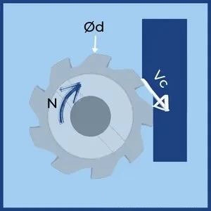
1. Calculation of milling speed
d——effective diameter
n – spindle speed
C – circumference
V c – cutting speed
theory:
Cutting speed is the relative linear speed between the cutting edge tip and the workpiece. It is the product of the speed of the cutter (spindle speed) and its circumference.

Tip: The diameter (d) should be the effective diameter and not the tool diameter. On 90° cutters both have the same value, however on round and chamfered cutters the effective diameter depends on the depth.
official:

d – [毫米]
n – [rpm](revolutions per minute)
Vc – [米/分钟]
2. Spindle speed calculation
How to calculate spindle speed based on cutter diameter and cutting speed

theory
The cutter manual or experience tells us what cutting speed should be used for a given operation. CNC machines, on the other hand, are programmed with spindle speed. Therefore, we often need to calculate the RPM based on a given cutting speed in order to program or ensure that the desired speed is within the limits of the machine tool. It is calculated by dividing the cutting speed by the tool circumference.

Tip: For accurate results, you should use the effective diameter. In a 90° milling cutter, this is simply the diameter of the tool. However, on round and chamfer cutters, the effective diameter depends on the depth of cut and tool geometry.
official

d – [毫米]
n – [rpm](revolutions per minute)
Vc – [米/分钟]
3. Calculation of the amount of feed per tooth

n – spindle speed
z——Number of teeth
F z – feed per tooth
V f – table power supply
theory:
Feed per tooth represents the load (chip load) acting on a single cutting edge of the cutter. It is a good indicator to check if certain cutting conditions (spindle speed and table feed) are reasonable for a given tool geometry. It is calculated by dividing the table feed by the spindle speed and the number of slots.
Tip: fz equals chip load only when the radial cutting depth of the 90° cutter is greater than the tool radius (ae>r). In other cases, you can use higher feeds depending on the chip thinning factor.
official

z——Number of teeth
n – spindle speed[RPM]
fz – feed per tooth[毫米或英寸]
fn – advance per revolution [毫米或英寸]
V f – table power supply[毫米/分钟]Or[英寸/分钟]
4. Calculation of feed rate
How to calculate feed rate based on feed per tooth, spindle speed and number of cutting edges.

theory
Milling feed (also called table feed and feed rate) is the linear speed of the cutter relative to the workpiece, given by [mm/min] Or [inch/min] as a unit. This is the actual parameter of the machine tool. It must be calculated based on the spindle rotation speed and the number of teeth. The parameters we can get from the tool manual are cutting speed and feed per tooth (chip load).
official

z——Number of teeth
n – spindle speed[RPM]
fz – feed per tooth[毫米或英寸]
fn – advance per revolution [毫米或英寸]
V f – table power supply[毫米/分钟]Or[英寸/分钟]
Tip: The main parameter that generates the table feed (Vf) is the feed per tooth (fz). A common mistake is to use chip load recommendations provided by tool manuals such as feed per tooth. However, this assumption is only correct when using a 90° cutter with a radial depth of cut greater than the tool radius (ae > r). In other cases you can use a higher fz depending on the chip thinning factor.
5. Material removal rate
theory
Material removal rate (MRR) is measured in cubic millimeters per minute and represents the amount of material machined in one minute under a set of cutting conditions. In milling, it is the product of the table feed, the radial depth of cut and the axial depth of cut.
MRR meets two objectives:
Compare productivity between two sets of cutting conditions.
Estimate the required power consumption.
official
![]()
ae – radial cutting depth [mm] Or [inch]
ap – axial cutting depth [mm] Or [inch]
Vf – table flow[毫米/分钟]Or[英寸/分钟]
Q – Metal removal rate [mm 3 /min] Or [inch 3 /min]
Daguang focuses on providing solutions such as precision CNC machining services (3-axis, 4-axis, 5-axis machining), CNC milling, 3D printing and rapid prototyping services.