1: Basic knowledge of mechanical drawing:
1: Reading and measuring the dimensions of the part:
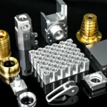
Basic tools for measuring the dimensions of parts in the workshop: tape measure and caliper.
1.1: The distance between a division of the tape measure is 1 mm.
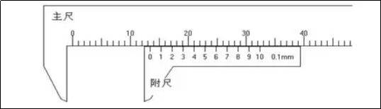
1.2: Vernier caliper reading method.
1.2.1 Take the 10-minute caliper reading as the column:
Correct pronunciation: three steps
1. Read the main scale value first. The accuracy is 1 mm. Scale “0” of the attached scale is between scales “13” and “14” of the main scale. is 13mm. 2. Then look at the attached ladder and the main ladder. The accuracy is 0.1mm (marked in the lower right corner of the attached ruler). the ruler overlaps the main ruler, so the scale of the attached ruler is 0.1X4=0.4 mm 3. Add the values of the main ruler and the attached ruler. The scale above represents 13.4mm.
The reading of the caliper is therefore: 13.4 mm.
1.2.2 Resetting the caliper to zero.

1.3 Briefly explain how to read qualified dimensions of parts marked with dimensional tolerances:
Qualified dimensional readings after marking the tolerances on the dimensions of the sheet metal parts. Let us explain in detail through the following examples.
Example 1:![]()
its meaning is as follows: +0.3 means taking the upper tolerance. -0.5 logo removed
Difference. Therefore, the qualified sizes are: 80-0.5 to 80+0.3, that is, 79.5 to 80.3 are qualified sizes.
Another example is 2:![]()
which means the qualified size is between 64-0.5 and 64+0.5. Or: 63.5
64.5 is the qualified size.
The other sizes are read by analogy.
1.4 The following is the contents of the title block of a drawing. The title bar is located in the lower right corner of the drawing frame, with the part name, drawing number,
The designer, material, etc. must be clearly expressed in the title bar.

2: Knowledge of mechanical drawing and comparison with the drawings, method of rapid recognition of the drawings of returned parts:
2.1 Mechanical Drawing Concept: Engineering used in design, manufacturing, inspection, installation, etc. mechanical products or equipment
The drawings are collectively called mechanical fabrication drawings, or mechanical drawings for short. They are essential technical documents in industrial production. 2.2 To understand mechanical drawings, you must first understand the view in the drawing, because it expresses the shape of the object. To understand how views are formed, you first need to understand projection. Projection requires four conditions: light source, projection line, object and projection surface. The sun shines on the trees and the sunlight casts the shadows of the trees on the ground. Among them, the sun is called a light source, the sun’s rays are called projection lines, trees illuminated by light are called objects, and trees are called objects. the ground where the shadow appears is called the projection surface. The shadow on the projection surface is the projection.
The method of using this principle to reflect spatial objects on a plane is called projection. If we assume that the light source is at infinity, so that the projection lines can be considered parallel to each other and perpendicular to the projection plane, this method of projection is called orthographic projection. The orthographic projection method can accurately express the shape of an object, has good measurability and is convenient for drawing, and is widely used in engineering. View: The graph of an object drawn using an orthographic projection is called a view.

The projections of objects that we see in our daily lives are all black shadows. As shown in Figure 1-1(a), the positioning plate uses an orthographic projection and the resulting projection appears as a black shadow. It can only express the outline of the positioning plate, so when looking at the front of the object, the central convex part in front cannot be expressed clearly. Therefore, when we use the principle of orthographic projection, we must use sight lines instead of projection lines and draw all contours of the object with prescribed drawing lines. The resulting plane figure is called a view, as shown in Figure 1-1. (b). The previously mentioned frontal view of an object is a popular term for obtaining a view using the principle of orthographic projection, that is, a view obtained by looking at an object with the line of sight perpendicular to the projection surface.

2.3 Three views of the object:
2.3.1 Graphics of an object drawn on a projection surface using the orthographic projection method can only reflect the shape of the object in one direction. Therefore, it is often expressed in three views. That is, the commonly used front view, top view and left view. The three-dimensional positions of the three projection planes of these three views are shown in Figure 1-2. These three projection surfaces are like a corner of the room, that is to say like two perpendicular walls and the floor.

2.3.2 Three projection planes and three views
Figure 1-3 is a part, which is a view obtained by projecting onto three projection planes from the front, top and left directions. Front View – the view drawn on the front projection surface, viewed from the front to the rear of the part. It reflects the shape and size of the room in length and height.
Left View – looking from left to right of the room, the view drawn on the side projection surface. It reflects the shape and size of the room in terms of width and height.
Top View: A view drawn on a horizontal projection plane looking down from the top of the room. It reflects the shape and size of the room in the direction of length and width.

In order to facilitate the viewing of the image, if you want to draw the three three-dimensional views on the same drawing, you need to unfold the three projection planes and flatten them on the same plane, as shown in 1-4. How to unfold it? Firstly, keep the front position unchanged, rotate the horizontal plane down 90°, then rotate the lateral side 90° to the right, in order to obtain the enlarged three-dimensional view.

2.3.3 The relationship between views (the relationship between three views)
Objects have three directions of length, width and height, as well as six directions of top to bottom, left to right, and front and back. Each view of the three views reflects the shape in two directions and in all four directions, as shown in the figure. 1-5. The main view reflects the thing

The length and height of the object and the four directions of the object (up, down, left and right); the top view reflects the length and width of the object and the four directions of the object (left, right, front and back). ); the left view reflects the height and width of the object and the object There are four directions: up, down, front and back; the shape, size and direction reflected by the three views are length, width, height and the same; direction of the same object. Now focus on the following: the left side of the left view (i.e. the side near the main view) represents the back of the object, the right side of the left view represents the front of the object and the width of the object from left to right in the left view is different from the top view compared to the width in .
As shown in the figure above (Figure 1-5), the two views jointly reflect the size of the object in the same direction, such as the front view and the top view. They both reflect the same length of the object. The front view and the left view reflect the same height of the object. The top and left views reflect the same width of the object. Therefore, the following “third class” relationship should be maintained between the three points of view, namely:
The left and right lengths of the main and top views are equal; the top and bottom heights of the main and left views are the same; the front and rear widths of the top and left views are equal.
In short, it means “the lengths are aligned, the heights are equal, and the widths are equal.”
2.4 How to read part drawings
In actual work, we often encounter the problem of looking at part drawings. Looking at the part drawing is to imagine the structural form of the part according to the content of the part drawing, and to understand the size and technical requirements of each part of the part, so as to formulate methods and procedures to process the part, or as a technical reference, and develop further on that basis. Studying the rationality of part structures allows for continuous improvement and innovation.
2.4.1 Have a general understanding of the role of parts on the machine
When you get a part drawing, start from the title bar, understand the name of the part drawing, understand its material from the material column, and estimate the actual size of the part from the overall drawing size. Based on existing practical knowledge, roughly understand its function. Understanding the function of parts and the relationship between related parts can lay the foundation for further analysis of the structural form, size and technical requirements of parts.
2.4.2 Analysis view. Determine the structural shape of the part
Imagining the shape of the part is one of the main purposes of observing the design of the part. The shape of the piece must be imagined and determined based on the content expressed by each graphic. When you look at an image, the line starts from the main view and then is viewed with other views. To understand the content expressed by each graph, you can proceed according to the following three steps:
(1) First understand how many views, partial views, section views and section views the part drawing you are looking at consists of and what is the relationship between them.
(2) Analyze the shape and use projection rules (third-order relationships) to analyze its components one by one until the shape of each part is understood.
(3) Through the above shape and structure analysis, when combined, we can imagine the general outline of the part, and then imagine its internal shape and the detailed structure of each part.
2.4.3 Review technical requirements and understand the processing process and manufacturing requirements
The technical requirements shown on the parts drawing are the quality requirements of the parts during processing, inspection and installation. From the surface roughness code, dimensional tolerance, geometric shape and mutual position tolerance shown in the picture, you can know the processing process and the main processing surface of the workpiece, and you can have a deeper understanding of the relationship between shape, structure and size of the part.
2.4.4 Synthesize, summarize and summarize to gain a comprehensive understanding of the parts.
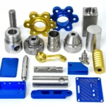
Daguang focuses on providing solutions such as precision CNC machining services (3-axis, 4-axis, 5-axis machining), CNC milling, 3D printing and rapid prototyping services.