1) Reference
Parts are composed of multiple surfaces, and each surface has certain requirements for size and mutual position. The relative position requirements between workpiece surfaces include two aspects: the dimensional accuracy of the distance between surfaces and the relative position accuracy requirements (such as coaxiality, parallelism, perpendicular and circular runout, etc.) . The study of the relative position relationship between the surfaces of the parts is inseparable from the data. Without clear data, the position of the part surface cannot be determined. In its general sense, a datum is a point, line or surface on a part used to determine the position of other points, lines or surfaces. Benchmarks can be divided into two categories: design benchmarks and process benchmarks based on their different functions.
1. Design Basis
The reference used to determine other points, lines, and surfaces on the part drawing is called the design reference. For the piston, the design reference refers to the centerline of the piston and the centerline of the pinhole.
2. Process benchmarking
The data used in the process of processing and assembling parts is called process data. Process marks are divided into positioning marks, measuring marks and assembly marks according to different uses.
1) Positioning data: The data used to make the workpiece occupy the correct position in the machine tool or fixture during processing is called positioning data. According to the different positioning components, the most commonly used are the following two categories:
Automatic centering and positioning: such as three-jaw chuck positioning.
Positioning sleeve positioning: transform positioning components into positioning sleeves, such as positioning stop plate
Others include V-shaped frame positioning, semi-circular hole positioning, etc.
2) Measurement data: When inspecting parts, the data used to measure the size and position of the processed surface is called measurement data.
3) Assembly Data: The data used to determine the position of parts in components or products during assembly is called assembly data.
2) How to install the part
In order to machine a surface meeting the specified technical requirements on a certain part of the workpiece, the workpiece must occupy a correct position on the machine tool relative to the tool before machining. This process is generally referred to as “positioning” the part. Once the workpiece is positioned, due to the effects of cutting force, gravity, etc. during processing, some mechanism must be used to “clamp” the part so that its determined position remains unchanged. The process of bringing the workpiece into the correct position on the machine tool and clamping the workpiece is called “setup.”
The installation quality of parts is an important issue in mechanical processing. It not only directly affects the processing accuracy, speed and stability of parts installation, but also affects the productivity level. To ensure relative positional accuracy between the machined surface and its design datum, the part must be installed so that the design datum of the machined surface occupies the correct position relative to the machine tool. For example, in the process of finishing the ring groove, in order to ensure the runout requirements of the bottom diameter of the ring groove and the skirt axis, the part should be installed so that its data of design coincide with the axis of the machine tool spindle. .
There are different installation methods when machining parts on various machine tools. Installation methods can be summarized into three types: direct alignment method, marking alignment method and clamp installation method.
1) Direct Alignment Method When using this method, the correct position that the workpiece should occupy on the machine tool is achieved through a series of attempts. The specific method is to directly install the workpiece on the machine tool, use a dial indicator or the needle on the needle plate to visually correct the correct position of the workpiece, and correct it while checking until that it meets the requirements.
The positioning accuracy and alignment speed of the direct alignment method depend on the alignment accuracy, alignment method, alignment tools and technical level of the worker. Its disadvantages are that it is time-consuming, has low productivity, must be operated based on experience, and requires high skills from workers, so it is only used in production unique pieces and small batches. For example, if you rely on imitating body alignment, this is a direct alignment method.
2) Marking and alignment method This method is to use a marking needle on the machine tool to align the workpiece according to the line marked on the blank or semi-finished product so that it can obtain the correct position. Obviously, this method requires an additional marking process. The drawn line itself has a certain width, and there are marking errors when marking and observation errors when correcting the position of the part. Therefore, this method is mainly used for small production batches, low blank accuracy and large parts where it is found. not suitable for using fixtures in rough machining. For example, the pinhole position of a two-stroke product is determined using the index head marking method.
3) Use fixture installation method: The processing equipment used to clamp the workpiece so that it occupies the correct position is called machine tool fixture. The device is an additional device of the machine tool. Its position relative to the tool on the machine tool was pre-adjusted before parts were installed. Therefore, when processing a batch of parts, there is no need to align and position them. one by one to ensure the technical requirements of the processing. It saves labor and trouble, is an efficient positioning method, and is widely used in batch and mass production. Our current piston processing uses the fixture installation method.
① After the workpiece is positioned, the operation of maintaining the position unchanged during processing is called clamping. The device device that holds the workpiece in a constant position during processing is called a clamping device.
②. The clamping device must meet the following requirements: when clamping, the positioning of the workpiece must not be damaged; after clamping, the position of the workpiece should not change during processing, and the clamping should be accurate, safe and reliable; It moves quickly, is easy to operate and labor-saving; it has a simple structure and is easy to manufacture.
③ Precautions when tightening: The clamping force should be appropriate. If it is too large, the part will warp. If it is too small, the part will move during processing and damage the positioning of the part.
3) Basic knowledge of metal cutting
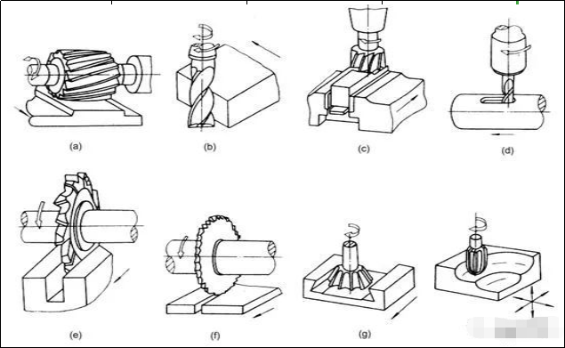
1. Rotational movement and formed surface
Turning Movement: During the cutting process, in order to remove excess metal, the workpiece and the tool must perform relative cutting movements. The motion of using a turning tool to remove excess metal on the workpiece on a lathe is called turning motion, which can. be divided into main movement and forward movement.
Main movement: The movement which directly removes the cutting layer on the workpiece and turns it into chips to form a new surface of the workpiece is called main movement. When cutting, the rotational movement of the workpiece is the main movement. Generally, the speed of the main movement is higher and the cutting power consumed is greater.
Feed motion: A motion that continually puts new layers of cutting into section. The feed movement is a movement along the surface of the part to be formed. It can be continuous movement or intermittent movement. For example, the movement of the turning tool on a horizontal lathe is a continuous motion, while the feed motion of the workpiece on a planer is an intermittent motion.
Surfaces formed on the workpiece: During the cutting process, the machined surface, the machined surface and the surface to be machined are formed on the workpiece. A machined surface is a new surface that has been machined without excess metal. The surface to be processed refers to the surface from which the metal layer is about to be cut. The machined surface refers to the surface turned by the cutting edge of the turning tool.
2. The three elements of cutting quantity refer to cutting depth, feed quantity and cutting speed.
1) Cutting depth: ap=(dw-dm)/2(mm) dw=diameter of unprocessed workpiece dm=diameter of processed workpiece Cutting depth is what we usually call cutting quantity.
Selection of the cutting depth: The cutting depth αp must be determined according to the machining allowance. When roughing, in addition to leaving a finishing allowance, the entire roughing allowance must be removed as much as possible in a single pass. This can not only make the product of cutting depth, feed ƒ and cutting speed V high while ensuring a certain degree of durability, but also reduce the number of tool passes. When the machining allowance is too large or the processing system has insufficient rigidity or the blade strength is insufficient, the tool passes should be divided into two or more passes. At this time, the cutting depth of the first pass should be larger, accounting for 2/3 to 3/4 of the total margin, and the cutting depth of the second pass should be smaller, so that the finishing process can achieve a smaller surface area; roughness parameter values and higher processing precision.
When cutting materials with high cold hardness, such as castings, forgings or stainless steel, with hard skin on the surface of the parts, the cutting depth should exceed the hardness or layer cold hard to prevent the cutting edge from cutting on hard or cold hard skin. layer.
2) Selection of the feed amount: for each rotation or reciprocating movement of the part or tool, the relative displacement between the part and the tool in the direction of the feed movement, in mm. Once the cutting depth is selected, a greater feed rate should be selected as much as possible. Selecting a reasonable feed value should ensure that the machine tool and tool will not be damaged due to too much cutting force, the workpiece deviation caused by the cutting force will not exceed not the value allowed by the precision of the part and that the surface The value of the roughness parameter will not be too large. During rough machining, the feed rate is mainly limited by the cutting force. In semi-finishing and finishing machining, the feed rate is mainly limited by the surface roughness.
3) Cutting speed selection: during cutting processing, the instantaneous speed of a certain point on the tool cutting edge relative to the surface to be processed in the main direction of movement, the unit is m/ min. After selecting the cutting depth αp and the feed amount ƒ, the maximum cutting speed is selected based on this. The development direction of cutting processing is high-speed cutting processing.

4) Concept of roughness mechanics
In mechanics, roughness refers to microgeometric features consisting of small spacings and peaks and valleys on the machined surface. This is one of the challenges of research on interchangeability. Surface roughness is usually caused by the machining method used and other factors, such as friction between the tool and the workpiece surface during the machining process, plastic deformation of the surface metal during chip separation and high frequency vibration in the processing system. . Due to different processing methods and workpiece materials, the depth, density, shape and texture of the marks left on the processed surface are different. Surface roughness is closely related to the adaptation properties, wear resistance, fatigue resistance, contact stiffness, vibration and noise of mechanical parts, and has an important impact on the lifespan and reliability of mechanical products.
Roughness representation
After processing, the surface of the part appears smooth, but when viewed under magnification, it turns out to be uneven. Surface roughness refers to microgeometric features consisting of small gaps and tiny peaks and valleys on the surface of processed parts. It is usually formed by the treatment method adopted and/or other factors. The functions of the workpiece surfaces are different, and the required values of surface roughness parameters are also different. The surface roughness code (symbol) must be marked on the part drawing to describe the surface characteristics that are to be achieved when the surface is completed. There are three types of surface roughness height settings:
1. Arithmetic mean contour deviation Ra
In sampling length, arithmetic average of the absolute value of the distance between points on the contour line along the measurement direction (Y direction) and the reference line.
2. Ten-point height of microscopic irregularities Rz
It refers to the sum of the average value of the five maximum contour peak heights and the average value of the five maximum contour valley depths over the sampling length.
3. Maximum contour height Ry
Distance between the upper line of the highest peak and the lower line of the lowest valley over the sample length.
At present, Ra is mainly used in the general machinery manufacturing industry.

4. Roughness representation method

5. The impact of roughness on part performance
The surface quality of the part after treatment directly affects the physical, chemical and mechanical properties of the part. The working performance, reliability and service life of the product largely depend on the surface quality of the main parts. Generally speaking, the surface quality requirements of important or critical parts are higher than those of ordinary parts, because parts with good surface quality will greatly improve their resistance to wear, corrosion and damage due to fatigue.
6. Cutting fluid
1) The role of cutting fluid
Cooling effect: Cutting thermal energy eliminates a large amount of cutting heat, improves heat dissipation conditions, reduces the temperature of the tool and workpiece, thereby extending the life of the tool and avoiding dimensional errors in the part due to thermal deformation. .
Lubricating effect: the cutting fluid can penetrate into the space between the workpiece and the tool, forming a thin adsorption film in the small space between the chip and the tool, thereby reducing the friction coefficient, thereby reducing the friction between the tool chip and the workpiece. , which reduces cutting force and cutting heat, reduces tool wear, and improves the surface quality of the workpiece. Lubrication is especially important for finishing.
Cleaning effect: The tiny shavings generated during the cleaning process easily adhere to the workpiece and the tool. Especially when drilling deep holes and reaming, chips are easy to get stuck in the chip groove, affecting the surface roughness of the workpiece and. the life of the tool. Using cutting fluid can quickly remove chips and ensure smooth cutting.
2) Type: There are two main categories of commonly used cutting fluids.
Emulsion: mainly plays a cooling role. The emulsion is obtained by diluting emulsified oil with 15 to 20 times water. This type of cutting fluid has high specific heat, low viscosity and good fluidity. Use this type of cutting fluid. Cutting fluid is mainly used to cool the tool and workpiece, increase tool life and reduce thermal deformation. The emulsion contains more water and has poor lubricating and anti-rust functions.
Cutting oil: The main component of cutting oil is mineral oil. This type of cutting fluid has low specific heat, high viscosity and low fluidity. Low viscosity mineral oils are commonly used, such as motor oil. , light diesel, kerosene, etc.
Daguang focuses on providing solutions such as precision CNC machining services (3-axis, 4-axis, 5-axis machining), CNC milling, 3D printing and rapid prototyping services.