Analyze the key factors that affect the deformation of the treatment of large parts in thin plates. By formulating a reasonable processing technological plan and by combining a large amount of process test data, we optimize the constraint relief process method, design special tools, let’s improve tightening methods and optimize paths Treatment, etc. On the other hand, processes improvement measures have been taken to effectively solve the problem of deformation control in the treatment of large parts in thin plates and provide an achievable process solution to meet the product design requirements.
1 preface
Currently, in large -scale electronic equipment, there are more and more installation racks with blind traffic jams, which are increasingly involved in thin, thin plates structures. Large parts in thin plates have the advantages of good integrity, compact structure and light weight. However, due to their low rigidity and low resistance, the processing process is affected by processing stresses, tightening conditions and movement trajectories of the tool, and they are easily deformed. It is therefore difficult to meet the design requirements, the subsequent application will affect the accuracy of the assembly, thus affecting the accuracy of the blind coupling and the electrical performance of the blind coupling connector.
In order to meet the design requirements of modules assembly by borgne plugs, deformation of the treatment of large parts in thin plates in the installation rack must be checked. The precision of the treatment of large parts in thin plates is mainly ensured by mechanical treatment[1]. By conducting research on deformation control technology for the treatment of large parts in thin plates, we can find reasonable process flows and methods that can improve the precision of the treatment of large parts in thin plates and meet the requirements design.
2 design precision requirements
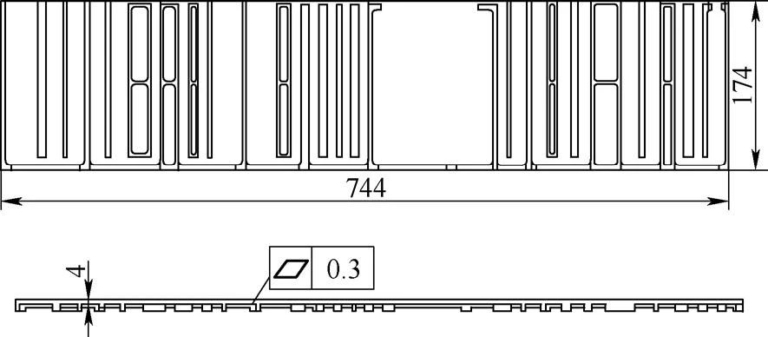
Figure 1 shows a typical rack mounting plate piece. It adopts a flat and open structure. The material is 2A12 hard aluminum. The overall dimensions are 744 mm × 174 mm × 11 mm. The surface of the part is the requirement is 0.3 mm. This room is a large, typical thin piece with large size, many thin walls, a high material removal rate and high precision requirements. Using conventional treatment technology, the global surface flatness can only reach 0.8 ~ 1 mm, which cannot meet the requirements. requirements.
Figure 1 A typical part of the rack mounting plate
3 Analysis of the main factors of influence of deformation linked to treatment
Many factors affect the deformation of the treatment of large parts in thin plates, in particular treatment constraints, tightening methods and movement trajectories of tools. When understanding the processing law is not very clear, it is necessary to analyze each factor and develop a special optimization verification plan for each factor.
3.1 Influence of transformation stress
When there are internal constraints in a room without any external force agrees on it, the internal constraints are balanced with each other. During the cutting and cold treatment of the parts, a cutting force and a cutting heat occur, the surface of the hard room and internal stresses appear in the metal on the surface layer. Once the stress layer has been removed, the constraint is redistributed, which will cause. deformation of these parts with thin walls.[2]. The conventional process of relief for constraints for such parts is a low -temperature heat treatment to relieve stresses. This process takes a lot of time and will also lead to a decrease in the resistance of parts, which is not conducive to the control of the deformation of treatment.
3.2 Influence of the tightening method
During the machining, before starting the treatment of the part, in order to prevent the part from moving under the action of the cutting force, correct tightening measurements must be taken. A certain tightening force will be generated during the tightening process. Since it is a constraint exerted by the outside world, it cannot be completely released during treatment. Therefore, when the tightening device is removed, the part can bounce and deform. The conventional tightening method for such large parts in thin plates is tightening by pressure plate. This method is a distributed multipoint tightening. The machining part is mainly affected by the axial compression force and part of the horizontal radial force.[3]. Due to the scattered and changing action points, it is difficult to ensure a uniform constraint on the part, which is not conducive to the control of deformations of treatment.
3.3 Influence of the trajectory of the movement of the tool
The movement trajectory of the tool (also called tool trajectory or supply trajectory) refers to movement trajectory and the position of the position of the tool in relation to the part to be machined during the process of ‘machining.[4]. In order to reduce machining deformation, when planning the tool course, the untreated part of the part must be used as much as possible as a support for the strawberry part, so that the cutting process is in a condition more rigid. Such parts are conventionally processed using the movement trajectory of the tool from left to right. During the final part of the treatment, the untreated part of the part forms a unilateral support, which does not allow to control the deformation linked to the treatment.
4 global solution
On the basis of the past treatment experience, in order to reduce the deformation of the part, an appropriate machining supplier is defined, the principle “a small quantity and several times” is adopted, coarse and fine machining is bunk And a constraint relief process is added after the removal process of more material. Details The process flow is as follows: Preparation of the material → Coarse planing → Relief of stresses → CNC Fraft draft → Constraint relief → CNC milling finish → Fine planing → Tightening → Surface treatment.
Given the key factors affecting treatment deformation, in terms of selecting specific processing method, different process analogy test plans are designed and, thanks to testing test data, the control method treatment deformation adapted to this type of large parts in thin plates is optimized. The test content includes a comparison of the constraint relief methods, a comparison of tightening methods and a comparison of the movement’s movement trajectories. The three aspects are combined to form 8 specific treatment routes. 2 process samples are defined for each processing route, and a total of. 16 process samples are tested. Save the change of the planees of the large area of the part during the test and analyze them. The detailed process test plan is presented in Table 1.
Table 1 Process test plan

5 Process tests
5.1 Comparison of stress relief
Determine the moment and the constraint relief method for 16 process samples as a function of the processing method. Determine that each sample must be relieved separately after coarse planing and coarse milling. After relaxing constraints, use a three -dimensional coordinate measurement instrument to detect it. flatness and save data. Among them, 8 pieces adopt the conventional method of relieving low -temperature constraints by heat treatment, and the other 8 parts adopt the method of relieving constraints due to aging by harmonic vibration, as shown in Figure 2.

Figure 2: Relief of constraints linked to vibratory aging
The results of the tests show that after a coarse planing, there is little difference in the flatness of the part between the two methods of relief of the constraints. After a coarse milling, the test tube using the aging method by harmonic vibration to eliminate the stresses has a smaller deformation than the sample using the thermal aging method. The elimination of the constraints of the sample is more complete and more uniform, and the control effect of deformation of the treatment is better. A set of tests for testing stress relief process test is presented in Figure 3.

Figure 3 Analysis of testing data for stress relief comparison
5.2 Comparison of tightening methods
When the parts are processed by CNC milling, the tightening method by vacuum suction cup and the tightening method by traditional pressure plate are compared. After the fine milling process, a three -coordinated measurement instrument is used to detect the flatness and the data is saved. For analysis. Among them, 8 pieces use the traditional tightening method by pressure plate, and the other 8 parts are designed with special vacuum suction cup tools and are tight using the vacuum suction cup method, like the shows Figure 4.

Figure 4 Tightening by vacuum suction cup
The results of the tests show that after having removed a large amount of material during coarse milling, the tightening method by vacuum suction cup is used during fine milling, the tightening force is distributed more uniformly, the vibrations are less likely to Performing during the cutting process and the flatness The control effect is better. Analysis of test data of a set of comparison of assembly tightening methods is illustrated in Figure 5.

Figure 5 Analysis of process test data to compare tightening methods
5.3 Tool movement trajectory comparison test
During coarse milling and strawberry finishing of parts, starting from the principle that the treatment parameters and processing methods are completely consistent, different tool movement trajectories are used for processing, the flatness is detected with an instrument to measure three -dimensional coordinates and the data is saved for analysis. Among them, the route of the 8 test Tool was treated in a conventional sequence from left to right, and the other 8 parts were treated in a sequence of the middle at both ends. The testing test of the movement trajectory of the tool is presented in. Graphics 6.

Figure 6 Tool movement trajectory comparison test
The results of the tests show that for the parts treated with two different tool movement trajectories, the difference is not obvious, whether it is the flatness value detected after the CNC milling process or the slope From each stage of the curve, proving that the difference in tool movement trajectories has a significant impact on this type of part. The influence of the deformation of the treatment of the part is not significant. A set of tests for testing processing processing process tests is presented in Figure 7.

Figure 7 Analysis of test data testing data comparison process comparison
6conclusion
This article analyzes the main factors of influence for controlling the deformation of the treatment of large parts in thin plates. By formulating reasonable processing plans and test plans and by testing effective process tests, a large amount of test data is obtained, which provides solid support for optimizing processing methods. The analysis of process test data shows that in terms of controlling the treatment of treatment of thin plates as large, the vibration aging process is more effective than the heat treatment process, and the method tightening using vacuum suction cups is better than the tightening method using pressure plates. Better results. The relevant search results will be transformed into process specifications and applied to the control of the deformation of these large parts in thin plates. By adopting new treatment methods, the flatness of the parts can be controlled in a stable way to the nearest 0.2 mm, thus meeting the design requirements.
The results of processes research show that improved processing technology can effectively improve the quality and efficiency of part processing, and has a good reference meaning for controlling the treatment of large parts in thin plates .
Daguang focuses on providing solutions such as precision CNC machining services (3-axis, 4-axis, 5-axis machining), CNC milling, 3D printing and rapid prototyping services.


