Skip to content

CNC Knowledge: FANUC alarm number, no more leafing through books.

FANUC 0MD System Alarm Instructions If you find it useful, just save it. You no longer need to browse books. 1. Alarm number of program alarm (P/S alarm) Alarm content 000 Settings that need to be turned off to take effect after being changed need to be turned off after changing the settings. 001 TH […]

Content Navigation

FANUC 0MD System Alarm Instructions If you find it useful, just save it. You no longer need to browse books.

1. Alarm number of program alarm (P/S alarm)

Alarm content

000

Settings that need to be turned off to take effect after being changed need to be turned off after changing the settings.

001

TH alarm, the program format entered by the device is incorrect.

002

TV alarm, the program format entered by the device is incorrect.

003

The entered data exceeds the maximum allowed entry value. Refer to relevant content in the programming section.

004

The first character of the program segment is not an address, but a number or a “-“.

005

An address is not followed by a number, but by another address or a program segment end character.

006

The “-” symbol is used incorrectly (“-” appears after an address that does not allow negative values, or two “-” appear consecutively).

007

The decimal point “.” is not used correctly.

009

A character appears in a position where it cannot be used.

010

An unusable G code has been ordered.

011

A cutting feed is not given as a feed rate.

014

A synchronous feed command appears in the program (this machine tool does not have this function).

015

Try to move all four axes simultaneously.

020

In arc interpolation, the difference between the distance from the start point to the end point to the center of the circle is greater than the value specified by parameter #876.

021

During circular interpolation, the movement of an axis that is not in the circular interpolation plane has been commanded.

029

The tool offset value in the offset number specified by H is too large.

030

When using tool length compensation or radius compensation, the tool compensation value in the tool compensation number specified by H is too large.

033

An intersection point has been programmed and cannot appear during tool radius compensation.

034

Circular interpolation occurs in the block where tool radius compensation is started or canceled.

037

An attempt was made to change the plane selection using G17, G18 or G19 in cutter radius compensation mode.

038

Since in tool radius compensation mode, the start point or end point of the arc coincides with the center of the circle, overcutting will occur.

041

Overcutting will occur during tool radius compensation.

043

An invalid T code was ordered.

044

Use instructions G27, G28 or G30 in canned cycle mode.

046

The P address in the G30 command receives an invalid value (it can only be 2 for this machine tool).

051

Unable to move occurs after auto corner cutting or auto corner rounding block.

052

The block after the automatic corner cutting block or the automatic corner rounding block is not a G01 command.

053

In the automatic corner cutting or automatic corner rounding block, the address after the symbol “,” is not C or R.

055

In the automatic corner cutting or automatic corner rounding block, the movement distance is less than the value of C or R.

060

When searching for the sequence number, the sequence number of the instruction was not found.

070

The program memory is full.

071

The desired address was not found or the specified program number was not found during program search.

072

The number of programs in the program memory is full.

073

An attempt was made to use an existing program number when entering a new program.

074

The program number is not an integer between 1 and 9999.

076

There is no P address in the M98 subroutine call instruction.

077

Subroutines are nested more than three times.

078

The program number or sequence number ordered in M98 or M99 does not exist.

085

When entering a program from a device, the input format or baud rate is incorrect.

086

When using the tape reader/punch interface for program input, the device’s ready signal is disabled.

087

When using the tape reader/punch interface for program input, CNC micro-signal professional cncdar, although the reading stop is specified, the input cannot stop after the reading 10 characters.

090

The reference point restoration operation cannot be performed normally because it is too close to the reference point or the speed is too low.

091

Manual return to the reference point was performed while automatic operation was paused (when there was remaining distance traveled or when an auxiliary function was being performed).

092

In the G27 command, when the command position is reached, we see that it is not the reference point.

100

PWE=1, prompt that after finishing changing the parameter, set PWE to zero and press the RESET key.

101

While editing or entering a program, the power is turned off while the CNC refreshes the memory contents. When this alarm occurs, PWE should be set to 1, turn off the power, and hold the DEL key when turning the power back on to clear the memory contents.

131

There are more than 5 PMC alarm messages.

179

The number of controllable axes defined by parameter No. 597 exceeds the maximum value.

224

An attempt was made to execute a programmable axis movement command before returning to the reference point for the first time.

2. Servo alarm alarm number

Alarm content

400

The servo amplifier or motor is overloaded.

401

The cruise control ready signal (VRDY) is deactivated.

404

The VRDY signal is not disabled, but the position controller ready signal (PRDY) is disabled. Under normal circumstances, VRDY and PRDY signals should exist at the same time.

405

Position control system error, return to reference point operation failed due to problems with the NC or servo system. Repeat the operation to return to the reference point.

410

When the X axis stops, the position error exceeds the set value.

411

When the X axis moves, the position error exceeds the set value.

413

The data in the X-axis error register exceeds the limit value, or the speed command received by the D/A converter exceeds the limit value (possibly due to parameterization errors).

414

X-axis digital servo system error, check diagnostic parameter No. 720 and refer to the servo system manual.

415

X-axis command speed exceeds 511875 sensing units/second, check CMR parameter.

416

X-axis encoder failure.

417

X axis motor parameters are incorrect, check parameters 8120, 8122, 8123 and 8124.

420

When the Y axis stops, the position error exceeds the set value.

421

When the Y axis moves, the position error exceeds the set value.

423

The data in the Y axis error register exceeds the limit value, or the speed command received by the D/A converter exceeds the limit value (possibly due to parameterization errors).

424

Y-axis digital servo system error, check diagnostic parameter No. 721 and refer to the servo system manual.

425

Y axis command speed exceeds 511875 sensing units/second, check CMR parameter.

426

Y axis encoder failure.

427

Y axis motor parameters are incorrect, check parameters 8220, 8222, 8223 and 8224.

430

When the Z axis stops, the position error exceeds the set value.

431

During Z axis movement, the position error exceeds the set value.

433

The data in the Z axis error register exceeds the limit value, or the speed command received by the D/A converter exceeds the limit value (possibly due to parameterization errors).

434

Z-axis digital servo system error, check diagnostic parameter No. 722 and refer to the servo system manual.

435

Z axis command speed exceeds 511875 sensing units/second, check CMR parameter.

436

Z axis encoder failure.

437

Z axis motor parameters are incorrect, check parameters 8320, 8322, 8323 and 8324.

3. Overtravel alarm alarm number

Alarm content

510

Positive soft limit exceeded on the X axis.

511

Exceeding the negative software limit on the X axis.

520

Positive soft limit exceeded on the Y axis.

521

Negative soft limit exceeded on the Y axis.

530

Positive soft limit exceeded on the Z axis.

531

Z axis negative soft limit exceeded.

4. Overheating alarm and system alarm. Alarm No. 700 is an over-temperature alarm for the main NC circuit board, and alarm No. 704 is an over-temperature alarm for the pin.

The other 6×× is an alarm for PMC system and 9×× is an alarm for NC system. If the user detects the above two alarms, please consult FANUC for maintenance immediately.

Daguang focuses on providing solutions such as precision CNC machining services (3-axis, 4-axis, 5-axis machining), CNC milling, 3D printing and rapid prototyping services.

Welcome to GreatLight Metal,Maximum Processing Size 4,000 mm

Precision Machining CNC Quote Online

Loading file

Upload Click here to upload or drag and drop your model to the canvas.

The model is too large and has been resized to fit in the printer's build tray. [Hide]

The model is too large to fit in the printer's build tray. [Hide]

The model is too large, a fitting printer is selected. [Hide]

The model is too small and has been upscaled. [Hide]

Warning: The selected printer can not print in full color [Hide]

Warning: obj models with multiple meshes are not yet supported [Hide]

Warning: Unsupported DXF entity  [Hide]

Warning: could not arrange models [Hide]


File Unit:      
Scale:
%
L × W × H:
X: × Y: × Z:  cm 
Rotation:
X: ° Y: °  

Model Stats:

Material Volume: cm3
Support Material Volume: cm3
Box Volume: cm3
Surface Area: cm2
Model Weight: g
Model Dimensions:
x x cm
Number of Polygons:
Number of Shapes:
Total Path: cm
⚡ Instant Quote for Precision Manufacturing

Submit your design files (STEP/IGES/DWG) and receive a competitive quote within 1 hour, backed by ISO 9001-certified quality assurance.

📋 How It Works

  1. Upload & SpecifyShare your 3D model and select materials (Aluminum/Stainless Steel/Titanium/PEEK), tolerances (±0.002mm), and surface treatments.

  2. AI-Powered AnalysisOur system calculates optimal machining strategy and cost based on 10+ years of automotive/aerospace data.

  3. Review & ConfirmGet a detailed breakdown including:
    - Volume pricing tiers (1-10,000+ units)
    - Lead time (3-7 days standard)
    - DFM feedback for cost optimization

Unit Price: 

Loading price
5 Axis CNC Machining Equipment
4 Axis CNC Machining Equipment
3 Axis CNC Machining Equipment
CNC Milling & Turning Equipment
Prototype and Short-Run Injection Moldings Exact plastic material as final design
Volume Metal Die Casting Services - Precision Cast Parts
Bridge the Gap From Prototype to Production – Global delivery in 10 days or less
Custom high-precision sheet metal prototypes and parts, as fast as 5 days.
Custom Online 3D Printing Services
Design Best Processing Method According To 3D Drawings
Alloys Aluminum 6061, 6061-T6 Aluminum 2024 Aluminum 5052 Aluminum 5083 Aluminum 6063 Aluminum 6082 Aluminum 7075, 7075-T6 Aluminum ADC12 (A380)
Alloys Brass C27400 Brass C28000 Brass C36000
Alloys Stainless Steel SUS201 Stainless Steel SUS303 Stainless Steel SUS 304 Stainless Steel SUS316 Stainless Steel SUS316L Stainless Steel SUS420 Stainless Steel SUS430 Stainless Steel SUS431 Stainless Steel SUS440C Stainless Steel SUS630/17-4PH Stainless Steel AISI 304
Inconel718
Carbon Fiber
Tool Steel
Mold Steel
Alloys Titanium Alloy TA1 Titanium Alloy TA2 Titanium Alloy TC4/Ti-6Al 4V
Alloys Steel 1018, 1020, 1025, 1045, 1215, 4130, 4140, 4340, 5140, A36 Die steel Alloy steel Chisel tool steel Spring steel High speed steel Cold rolled steel Bearing steel SPCC
Alloys Copper C101(T2) Copper C103(T1) Copper C103(TU2) Copper C110(TU0) Beryllium Copper
Alloys Magnesium Alloy AZ31B Magnesium Alloy AZ91D
Low Carbon Steel
Alloys Magnesium Alloy AZ31B Magnesium Alloy AZ91D
ABS Beige(Natural) ABS Black ABS Black Antistatic ABS Milky White ABS+PC Black ABS+PC White
PC Black PC Transparent PC White PC Yellowish White PC+GF30 Black
PMMA Black PMMA Transparent PMMA White
PA(Nylon) Blue PA6 (Nylon)+GF15 Black PA6 (Nylon)+GF30 Black PA66 (Nylon) Beige(Natural) PA66 (Nylon) Black
PE Black PE White
PEEK Beige(Natural) PEEK Black
PP Black PP White PP+GF30 Black
HDPE Black HDPE White
HIPS Board White
LDPE White
This is a finish of applying powdered paint to the components and then baking it in an oven, which results in a stronger, more wear- and corrosion-resistant layer that is more durable than traditional painting methods.
No coating required, product’s natural color!
This is a finish of applying powdered paint to the components and then baking it in an oven, which results in a stronger, more wear- and corrosion-resistant layer that is more durable than traditional painting methods.
This finishing option with the shortest turnaround time. Parts have visible tool marks and potentially sharp edges and burrs, which can be removed upon request.
Sand blasting uses pressurized sand or other media to clean and texture the surface, creating a uniform, matte finish.
Polishing is the process of creating a smooth and shiny surface by rubbing it or by applying a chemical treatmen
A brushed finish creates a unidirectional satin texture, reducing the visibility of marks and scratches on the surface.
Anodizing increases corrosion resistance and wear properties, while allowing for color dyeing, ideal for aluminum parts.
Black oxide is a conversion coating that is used on steels to improve corrosion resistance and minimize light reflection.
Electroplating bonds a thin metal layer onto parts, improving wear resistance, corrosion resistance, and surface conductivity.
This is a finish of applying powdered paint to the components and then baking it in an oven, which results in a stronger, more wear- and corrosion-resistant layer that is more durable than traditional painting methods.
Please provide additional text description for other surface treatment requirements!
Material
Material
  • CNC Metals
    • Aluminum
    • Brass
    • Stainless steel
    • Inconel718
    • Carbon Fiber
    • Tool Steel
    • Mold Steel
    • Titanium
    • Alloy Steel
    • Copper
    • Bronze
    • Low Carbon Steel
    • Magnesium
  • CNC Plastics
    • ABS
    • PC
    • PMMA (Acrylic)
    • PA (Nylon)
    • PE
    • PEEK
    • PP
    • HDPE
    • HIPS
    • LDPE
Printer
Printer
  • CNC Metals
    • 5 Axis CNC Machining
    • 4 Axis CNC Machining
    • 3 Axis CNC Machining
    • CNC Milling & Turning
    • Rapid Tooling
    • Metal Die Casting
    • Vacuum Casting
    • Sheet Metal Fabrication
    • SLA 3D Printing
    • SLS 3D Printing
    • SLM 3D Printing
  • Rapid Prototyping
    • Design Best Processing Method According To 3D Drawings
Post-processing
Post-processing
Finalize
The world's first CNC machining center that dares to provide free samples!

Free for first product valued at less than $200. (Background check required)

Precision Machining CNC Quote Online

15 Years CNC Machining Services

When you’re ready to start your next project, simply upload your 3D CAD design files, and our engineers will get back to you with a quote as soon as possible.
Scroll to Top
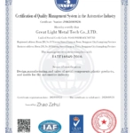
GreatLight Metal ISO 9001 certification successfully renewed
✅ ISO 9001:2015
GreatLight Metal ISO 9001 certification successfully renewed ZH
GreatLight Metal Technology Co., Ltd Has Obtained Multiple Certifications (3)
GreatLight Metal Technology Co., Ltd Has Obtained Multiple Certifications (4)
GreatLight Metal Technology Co., Ltd Has Obtained Multiple Certifications (1)
GreatLight Metal Technology Co., Ltd Has Obtained Multiple Certifications (2)
Automotive Industry Quality Management System Certification_01
Automotive Industry Quality Management System Certification_00
GreatLight Metal ISO 9001 certification successfully renewed
✅ ISO 9001:2015
GreatLight Metal Technology Co., Ltd Has Obtained Multiple Certifications (1)
GreatLight Metal Technology Co., Ltd Has Obtained Multiple Certifications (3)
Automotive Industry Quality Management System Certification_01

Get The Best Price

Send drawings and detailed requirements via Email:info@glcncmachining.com
Or Fill Out The Contact Form Below:

All uploads are secure and confidential.