3D printingHoles are almost everywhere. They are necessary for pins, bolts, bearings, linear rods and many other mechanical components. Without them, assemble some3D printing can be a nightmare of messy glue rolls and tape.
Although inDesigning a hole in CAD software takes just a few clicks, but mastering 3D printed hole design requires some experience. For example, how should the design of vertical holes (perpendicular to the print bed) differ from horizontal holes (parallel to the print bed)? What if the hole needs to be tapped?
From direction to material removal,Hole design for 3D printing involves many complex factors, resulting in very different adjustments in the final print.
In this guide,magic monkey networkWillLearn with everyonerelatedBest Tips for 3D Printing Holes. Finally, you will master a range of tools for making holes for different purposes. Let’s get started!
Master the basics: correct calibration


Showing elephant feet3D printing (Source: MatterHackers)
The first key to accurate hole drilling is correct calibration3D printer. There are many ways to calibrate, here are four that you should pay special attention to:
step per millimeter: The steps per millimeter setting indicatesWhat is the rotation of each motor for each millimeter of movement of the 3D printer. If these settings are incorrect, your printer will consistently produce holes that are too large or too small. Luckily, we have a dedicated calibration guide to help you find the right steps per millimeter setting for your machine.
Tree alignment: Axis orthogonality refers to the square of the printer’s axis of motion relative to other axes of motion. If they are not perfectly vertical, the movement of the printer will be skewed and the resulting holes will be slightly oval. To test orthogonality, use our recommended calibration cube with dowels. From there, physically adjust the printer’s axes until they are perfectly vertical.
First level calibration: As you may have noticed, the first layer of a 3D print is critical to the success of the print. Especially for holes, it is essential to avoid nailing the first layer“Elephant foot” is critical, which is when the print starts too close to the bed surface. This will affect the size of the hole opening, resulting in poor subsequent assembly results.
appropriate authorization: Each machine has slightly different precision, so parts cannot always be expected to fit together perfectly. This is where clearances come into play; these are tiny gaps in the design that ensure there is enough room for a proper fit.
Once you’ve completed these four steps, you’re ready to start designing! Here are some tips to help you succeed in your creationFive tips for 3D printing holes.
1、Don’t start in the air


a series of short and long3D printed bridge (Source: UltiMaker)
if applicable,3D printers can print bridges. A bridge (pictured above) stretches the plastic from one end of the gap to the other, reducing the chance of material dangling in the middle. But if you drill a hole in the deck, you disrupt this delicate balance, so the plastic can’t pass directly through the perimeter of the hole – the circle – must be expelled into the air, leaving nothing behind. to stick to. This can create a catastrophic mess with the unsupported print path, ruining your print or causing it to fail altogether.
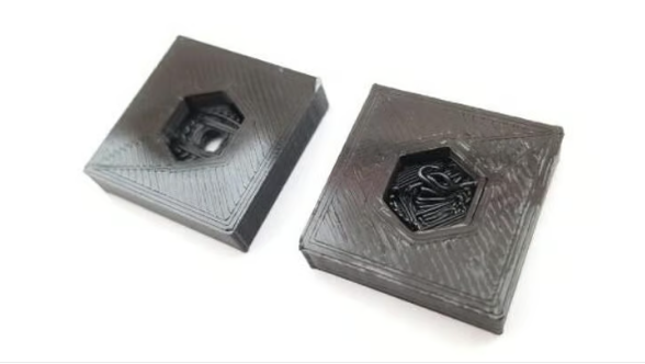

A modified air hole (left) and a failed, unmodified hole (right) (Source:Shop3D.ca)
There are generally two ways to resolve this problem.
First, some users like to break the hollow holes so that they rest on a series of straight bridges. As shown in the image above, the perimeter of the hole can rest on a series of surrounding layers, preventing the aforementioned air-printing phenomenon. The result is a neater, support-free product.
Additionally, some users prefer to use one or two layers of plastic“Filling” the hole essentially seals the bottom of the hole to form a flat bridge. Simply add this thin layer of plastic and the hole will be well supported from underneath and can be cut out later with an X-acto knife. From a design perspective, this option is also easier to implement than the previous option.
2、Beware of shrinkage
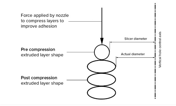

Visual compression of extruded layers, resulting in undersized holes (Source:Hubs)
The withdrawal isAnother important consideration for 3D printed holes. Although shrinkage can occur in different ways, the result is always the same: the hole will be slightly smaller than expected. Although this change is subtle, it is enough to distinguish a bolt that is too tight from one that slips all the way through.
There are three main reasons for withdrawal:
material removal: The material will shrink as it cools. This is the cause of many notorious print failures, including layer warping and delamination. For holes, this shrinkage can result in parts that are slightly undersized and don’t fit together properly.
layer compression: This condition causes the hole to shrink, but is actually caused by too much coating. When the printer lays down a new layer, it applies a compressive force (as shown in the image above). Although this increases the strength of the part, the lower layers are also compressed slightly beyond their original limits. The result is that the printed part looks too sharp in all directions.“Swell”, including inside the hole.
grid resolution: Although technically not a“Shrinkage”, but the grid resolution causes the printed holes to be smaller than originally designed. The key here is that with most 3D printing files, the “holes” are not actually perfect circles, but rather an approximation made up of polygons. The result is a bit of cutting at the corners, making the printed hole smaller than originally designed.


Manufacturers employ various tricks to solve shrinkage problems (Source:hartk1213 via Reddit)
To solve these problems, you can start by designing the hole slightly larger to avoid shrinkage. After printing, the holes will become smaller and closer to the ideal size. It may take some trial and error to find the sweet spot, but you’ll likely find a mistake that will lead to the ideal fit.
Alternatively, you can also experiment with adjusting the material shrinkage in the slicer. Although different tools have different names, there is usually an option to specify filament removal. Similar settings are available“Horizontal expansion”, which also prevents shrinkage by automatically expanding or shrinking the model before printing.
Finally, you always have the option of leaving the hole as is (or even slightly smaller than the original size). This will give you some room for the screw to bite if you plan to hammer the threads; otherwise, you can simply drill the holes to the exact dimensions you need.
3、avoid overhang


The teardrop shape allows for printing without sagging of horizontal holes (Source:flowalistics via Wikifactory)
Most of what we’ve discussed so far applies to vertical holes. What to do if you encounter a horizontal hole? In this case, your maximumchallengeMaybe it’s the overhang.
As shown in the image above, the overhang created by a horizontal hole becomes increasingly steeper as the hole closes. When printing, this means the top of the hole can easily sag, causing the opening to sag slightly.“Squash”. This is enough to block the opening if you want to insert the bolt.
Fortunately, this problem is easily solved by using a teardrop hole instead of a completely round hole (as shown in the image above). This design avoids hole overhang, allowing the print to maintain the desired curvature. While this technique can slightly increase the complexity of a 3D design, it’s a small price to pay for an accurate end product.
4、Add a binding/compliance mechanism


Insert the linear rod into the slot and tighten to ensure a secure fit (Source:Maker’s Muse via YouTube)
In some cases you may need a hole that tightly surrounds the object. When installing the bearing or rod onThis often happens when 3D printing parts. How to find a balance between ease of assembly and solidity of the installation?
In this case, the best option might be to design the hole with a small margin. This makes it easier to insert components without sacrificing too much“Grip” and stability. There are generally two types of designs:
Fixing device: These devices make the original hole large enough for greater comfort when tightening later. A common design approach is to add a slot along the length of each hole, as shown above. Based on this, bolts can be used to fill gaps and tighten objects.
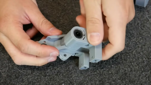

Bearings inserted using a flexible bore mechanism (Source:Maker’s Muse via YouTube)
compliant agency: If alignment is a problem (as with linear bearings), a compliant mechanism may be better suited to your application. These mechanisms rely on the natural elasticity of the plastic to provide some play in the hole size, allowing for a friction fit. You can see it in action above; the elasticity of the plastic provides enough space for the bearings.
5、Adjust with tools
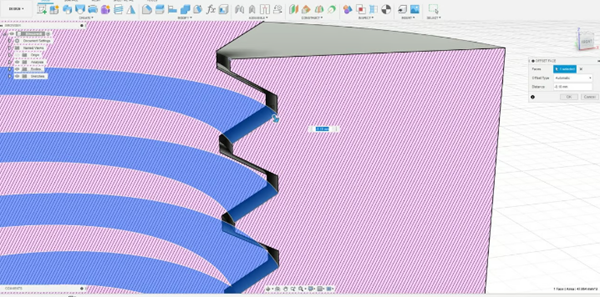

Use push-pull tools to improve the fit of threaded holes (Source:Hironori Kondo via All3DP)
So far we’ve mainly focused on bare, clean holes, but that doesn’t cover everything. Sometimes you may need threaded holes. These holes can be threaded directly into the bolts without the need for separate tappings or nuts. While this is convenient, it also makes many of the previous tips useless. For example, it is difficult to prevent shrinkage because bolt threads come in standard sizes.
To solve this problem, we need to creatively adjust the hole design. A good way is to use push/Pulling tool to widen the gap between the bolt and threaded hole, effectively increasing the clearance. You can combine this with the pinch adjustment above to fine-tune the fit.
When designing, please note that larger wires will come out more cleanly, especially whenon FDM 3D printer. We recommend printing with a lower layer height to create more precise threads.
Daguang focuses on providing solutions such as precision CNC machining services (3-axis, 4-axis, 5-axis machining), CNC milling, 3D printing and rapid prototyping services.


