1 Preface
Residual chips have always been the main reason for poor cylinder head cleaning. How to effectively avoid residual chips inside the engine cylinder head during processing is of great importance.
2 Context of the problem
The AF50 process for the EA888 engine cylinder head is carried out in a twin-spindle machining center in Germany. The machining center can clamp two cylinder heads at the same time on the A-axis support (see Figure 1). The tools on the machining center spindle simultaneously perform milling, drilling, reaming and tapping of cylinder heads. time, with the characteristics of high flexibility, high efficiency and high automation. During actual processing, residual chips are often found in the water channel hole of the cylinder head processed during this process (see Figure 2). If it is not discovered in time, the chips will block the water channel holes after assembling the engine, resulting in serious consequences such as improper operation of engine cooling water circulation. . Currently, operators participating in the final inspection process perform a 100% visual inspection of the cylinder head, which is time-consuming and labor-intensive. Due to the special structure of the water channel, it is not possible to ensure that the deeply hidden chips are completely uncovered during visual inspection, resulting in greater quality risk. Since March 2020, at least 8 quality defects caused by residual chips in the water channel holes have been discovered during engine warranty analysis.
Figure 1 Engine cylinder head


Figure 2 Chips remaining in the cylinder head water channel hole
3 Problem analysis
To solve the problem of chips remaining in the water channel hole, we must first find out how the chips enter the water channel hole of the cylinder head. Careful analysis of the process map of this process and the tool processing setting diagram of each step of the process revealed that this process is to process the hole system on the upper and lower planes of the cylinder head, but that there is no processing content on either end. surfaces of the cylinder head where the water channel holes are located. It is impossible to determine where the chips are coming from based on previous machining experience. Therefore, consider whether the source of the chips can be found through observation of the machining process. The AF50 process uses high-speed cutting to process the cast aluminum cylinder head, and the machine tool is equipped with an electric spindle and an internal coolant tool holder. The rotation speed of drill bits generally reaches more than 15,000 rpm. The cutting fluid inside the drill bit is atomized in the processing area at such a high rotation speed, and it is impossible to clearly see the chip splashes during processing by naked eye observation. Use CNC simulation software to simulate the machining process and determine which tools may cause chip residue. After measuring and mapping the machine tools, fixtures and cutting tools, they are imported into the CNC simulation software to create a CNC simulation system, as shown in Figure 3.


Figure 3 Creating a CNC simulation system
After simulating the processing state of each tool, it was found that the problem was previously considered based on the mindset of cylinder head processing alone, while the special situation of double spindle processing was ignored. Based on the simulated tool machining attitude (see Figure 4), we assume that the remaining chips are generated when the T1057 carbide twist drill processes the cylinder head check valve hole. Since the blank structure of the check valve hole is drilled, the chips splash from the drilled hole into the water channel hole of the cylinder head on the other side under the action of chip removal pressure of the cutting fluid of the internal coolant and the centrifugal force of the high-speed rotation of the tool. The chips remaining in the cylinder head water channel hole were sampled and compared to the cutting edge of the T1057 twist drill (see Figure 5). It was found that the width of the chips matched the width of the cutting edge of the T1057 twist drill. the drill. The chip is tapered and has a crease in the middle, dividing the chip into two sections with different tapers. This is completely consistent with the position of the turning point formed on the chisel edge and the main cutting edge of the T1057 twist drill.


a) State 1


b) State 2
Figure 4 Simulated tool machining attitude


Figure 5 Comparison of chips and drills
The existing technical solutions to solve the problem of chips in water channels are mainly as follows.
(1) Change the processing technology The current technology is to pre-mold the water outlet of the cylinder head when the blank is cast. The AF40 process is used to drill the water outlet hole of the cylinder head, and the AF50 process is used to drill the check valve hole. In order to prevent chips from the check valve hole from splashing into the water outlet hole of the cylinder head on the other side, the process can be changed as follows: no prefabricated holes are left during casting of the blank afterwards; The check valve hole is processed in AF50 process, then it is processed in AF130 process. The process involves “drilling and reaming” the water hole. However, this solution will cause an imbalance in the working hours of each process. The water outlet holes will not be prefabricated in the blank and an additional drill bit will be required to pre-drill the blank.
(2) Optimize tool T1057 to add chip grooves to turn chips into chips. But tiny shards can still wash into waterways.[1]。
(3) Increasing the fixed point flushing time and adjusting the nozzle angle will extend the process cycle of the cleaning machine. Cleaning with high pressure water can carry the chips into deeper waterways.
4 solutions
Design and produce a chip retainer for mounting the double spindle machining center (see Figure 6) to fundamentally prevent the chips from splashing from the drill hole to the situation in the water channel hole of cylinder head no. 2. The isometric view of the chip protection device is shown in Figure 7. It has the following structural features.


a) Overall structure


b) Principle of protection against fleas
Figure 6 Flea Protection Device
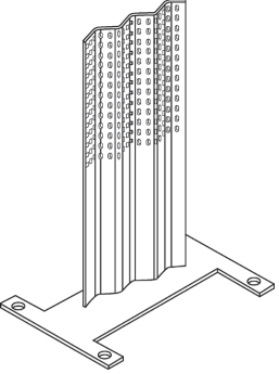

Figure 7 Isometric view of chip protection device
1) The chip protection plate of the chip protection device is corrugated, and the angle between the two hypotenuses of the corrugated plate is 120°±2° (see Figure 8). This allows the cutting fluid containing chips ejected from the check valve hole to produce a turbulent vortex and quickly dissipate most of the kinetic energy. It can not only prevent chips from splashing into the water outlet hole of No. 1 cylinder head, but also prevent chips from being bounced by the baffle into the cover hole of No. 2 cylinder head.
2) The chip deflector in the chip deflector and the x-axis of the device are tilted by 10° ± 2° (see Figure 8), which can cause the cutting fluid containing the chips and residual kinetic energy to be ejected from hole No. Cylinder head check valve 1 to Bounce in an oblique direction may cause a small amount of chips to be thrown onto the chip guard and bounce back to splash at the position of the No. 2 cylinder head cover hole.


Figure 8 Top view of chip protection device
3) The chip guard plate of the chip guard device has a pressure relief hole. The decompression hole is a waist-shaped hole whose long axis is perpendicular to the horizontal plane (see Figure 9). The waist-shaped hole shape can ensure the rigidity of the baffle and avoid stress concentration.[2]and can ensure the decompression of the cutting fluid. The size of the waist-shaped hole is smaller than the size of the chips, which can ensure that the chips are intercepted and allow the intercepted chips to fall by their own gravity when reversing the fixture.
4) Use the threaded holes on the original clamps for connection without damaging the original clamps.[3]。


Figure 9 Chip Guard Pressure Relief Port
5Conclusion
The chip protection device can effectively solve the problem of residual chips in the water channel hole of the engine cylinder head during machining.
1) The flea protection device has a simple structure and is easy to install. No modification to the original fixture is required.
2) The flea protection effect is reliable. After installation, the risk of chips in the water channel holes is basically eliminated.
3) It can reduce the visual inspection workload of final inspection personnel and reduce labor intensity.
Daguang focuses on providing solutions such as precision CNC machining services (3-axis, 4-axis, 5-axis machining), CNC milling, 3D printing and rapid prototyping services.


