1 Preface
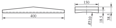
The structure of the pad for assembling the large roller on the WD615 series rotary kiln is shown in Figure 1. The R510mm arc groove on the backing plate is usually processed on a planer after scribing, or on a lathe vertical using a clamping tool. The former has low processing efficiency and low precision; the second, although the processing efficiency and precision are high, requires the investment of special clamping equipment, and the clamping is troublesome and the processing cost increases, making it unsuitable for the production of one piece. .
Figure 1 Buffer structure
After research, a simple processing method was adopted, using a milling cutter on an ordinary milling machine or boring machine, which improved the production efficiency and the precision fully meets the use requirements.
2. Processing method of arc groove of backing plate
The processing of the arc groove of the backing plate is shown in Figure 2. By tilting the cutter disk at an angle θ, the arc groove can be processed by controlling the distance between the cutter disk and the workpiece to guarantee the depth of the arc; groove. The processing process is shown in Figure 3.

Figure 2 Schematic diagram of arc groove processing of support plate

Figure 3 Treatment process
Analysis of the principle: when the inclination angle θ is 0°, the radius of the processed arc groove is the radius of the cutter; when the inclination angle θ is 90°, the radius of the processed arc groove is infinite, which is a plane. ; when the inclination angle When the angle θ is between 0° and 90°, the processed arc groove is actually an elliptical arc groove whose long axis is the diameter of the cutter disc and the Short axis is the product of the diameter of the cutter disk and the cosine of the tilt angle. In terms of accuracy, if possible, it can be approximated as an arc groove.[1]。
3. Method for determining the angle of inclination
According to the simple processing method, the key is how to determine the specific inclination angle θ of the cutter disc. Draw an ellipse according to the four-center approximation shown in Figure 4.[2]assuming that the major semi-axis of the ellipse is a and the minor semi-axis is b, through simple mathematical calculation, the radius of the major arc R of the ellipse can be calculated[3]


Figure 4 Approximate four-center ellipse drawing method
In Figure 2, the long axis of the ellipse is the diameter d of the cutter disk and the short axis is dcosθ. Replacing equation (1), we can deduce that the relationship between d, θ and R is as follows.

For a specific workpiece, the radius R of the arc groove is known and the diameter d of the cutter disc is also known. The inclination angle can be calculated by substituting into equation (2). Of course, the calculation process is very tedious. You can compile a calculation formula on Excel to easily calculate the specific value of the inclination angle θ.
4 Error analysis
Since the above simple processing method actually approximately replaces the arc surface with an elliptical arc surface, it is necessary to study its theoretical error.
The point furthest from the center line has the largest error. The theoretical error can be calculated by calculating the coordinate values of the point according to circular arcs and elliptical arcs respectively. If it is within the allowed error range, it can be processed. in this way; if it exceeds In order to determine the allowable error, the theoretical error can be reduced by increasing the diameter of the cutter disc and reducing the tilt angle until the requirements are met.
The specific calculation process is complicated. The easiest way is to draw and measure directly in CAD, which can quickly and easily determine the theoretical error value.
The arc groove of the backing plate in Figure 1 uses a φ250mm cutter disk, and the inclination angle calculated according to equation (2) is 76.9353°. When drawing and measuring in CAD, the error at the farthest point from the center line is only 0.1064mm, which meets the requirements.
5 things to note
Since this simple processing method uses elliptical arc grooves to approximately replace arc grooves, in order to ensure accuracy, the following points should be noted when using this method.
1) The diameter of the selected cutter disc should be greater than the arc groove width (i.e. chord length) required by the workpiece.
2) The width of the arc groove of the workpiece should be less than the chord length B of the large arc of the ellipse in Figure 4. The formula for calculating the B value is as follows

3) Theoretical error value should be determined before use. This method can only be used when the accuracy requirements of the part are met.
6Conclusion
This article presents a simple method for processing large radius arc grooves on ordinary milling or boring machines. By controlling the inclination angle of the cutter disc, the surface of the elliptical arc is used to obtain rough processing of arc grooves, and the following conclusions. are drawn.
1) Using simple processing methods to process large radius arc grooves that meet precision requirements can improve production efficiency and reduce production costs.
2) For processing large radius arc grooves with low precision requirements, arc grooves of different radii can be processed by adjusting different inclination angles while the diameter of the cutter disc remains unchanged, thereby reducing saving tool specifications. reduce production costs.
3) The simple processing method is especially suitable for the production of single parts and small batches.
Expert commentary
The paper presents a simple method for processing large-radius arc grooves on ordinary milling machines or boring machines, and derives the formula for calculating the inclination angle of the milling cutter disk and the method for determining the theoretical error. Very suitable for the production of single pieces and small batches.
The article content has some technical heritage and process innovation. The method is simple, economical and practical. It fully exploits the advantages of ordinary machine tools and traditional processing by controlling the specific inclination angle of the milling cutter disc. the elliptical arc surface is used to approximately replace the arc surface processing, thereby reducing tool costs and improving production efficiency.
Daguang focuses on providing solutions such as precision CNC machining services (3-axis, 4-axis, 5-axis machining), CNC milling, 3D printing and rapid prototyping services.


