When designing equipment, when mounting materials, it is necessary to position and clamp the materials. The aim is to ensure the accuracy and stability of the materials. Provide a stable condition for the next operation. Let’s learn several types of workpiece tightening and loosening mechanisms.
To tighten the part, we usually need to analyze the nature of the part. Is the part soft or hard? Is the material plastic, metal or other materials? Should it be antistatic? Tightening? How much force can he bear. What material to choose.
1. Workpiece clamping and release mechanism
principle:
(1). Automatic cylinder mechanism. Press the hinge slider through the push rod installed on the cylinder to release the part.
(2) Tightened by a tension spring installed on the part support.
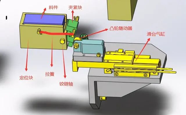

1. Place the material into the profiling positioning block and position it.
2. The sliding cylinder moves back, and the clamping block clamps the material under the action of the tension spring.
3. The rotating platform rotates to move the positioned materials to the next station for processing or assembly.
4. The sliding cylinder extends, the cam follower presses the lower end of the positioning block, and the positioning block rotates along the hinge and opens, so that materials can continue to be fed in.
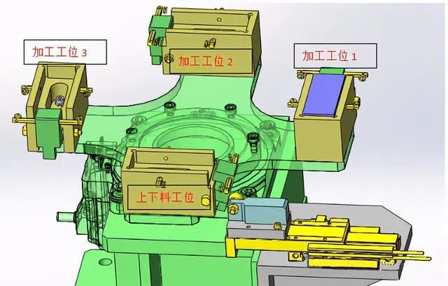

This image is only used for reference in principle to give an idea. If design is required, it should be designed according to the specific situation.
In order to improve production efficiency, multiple stations are generally used in processing and assembly. The picture shows 4 stations loading, processing and mounting do not affect each other, that is, loading does not affect processing and mounting. The placement between stations 1, 2 and 3 takes place simultaneously without influencing each other. This type of mental design greatly improves efficiency.
2. Inner diameter tightening and releasing mechanism based on connecting rod structure
(1) The inner diameter of the coarse guide part is clamped by spring force.
(2) Use the external push rod to push the linkage mechanism to the tight state to release it.
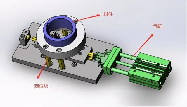

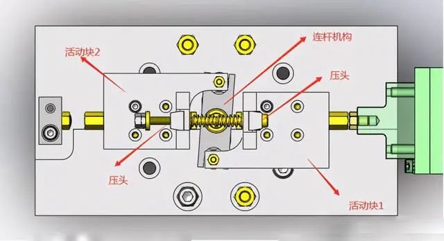

1. When the cylinder extends, the cylinder pushes the movable block 1 to move to the left. Under the action of the linkage mechanism, the movable block 2 moves to the right synchronously, and the left and right pressing heads move to the middle synchronously. .
2. Place the material into the positioning block and position it correctly. The cylinder retracts, and the left and right pressure heads are pushed by the spring to move the pressure heads on both sides and push the material firmly on both sides at the same time.
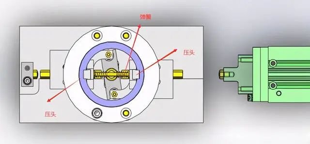

The diagram is only used for reference in principle to give an idea. If design is required, it should be designed according to the specific situation.
The force of the indenter is proportional to the amount of spring compression. Replace the spring or adjust the amount of compression to adjust the force of the indenter to push the material to prevent the material from being crushed.
3. Bearing clamping mechanism
Tightened by spring force, released by external piston.
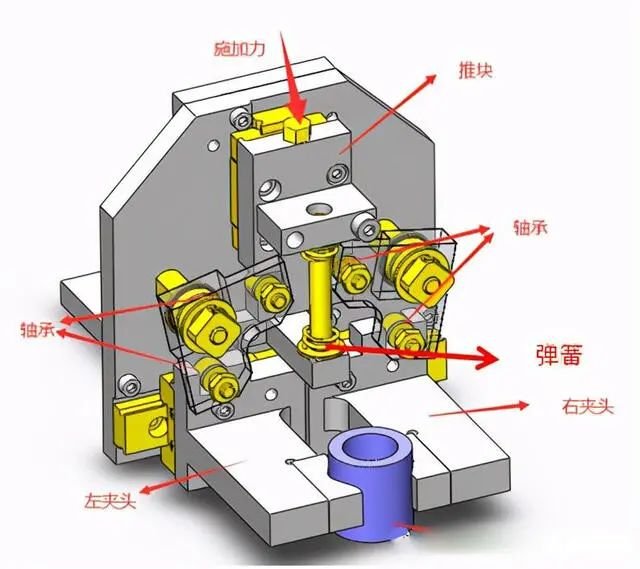

1. Apply force to the pusher block and the pusher block moves down. The pusher block pushes the two bearings into the groove of the pusher block. The fixed block of the bearing rotates clockwise along the axis of rotation, causing the left and right chucks to open towards both. sides.
2. When the force on the push block is canceled, the spring pushes the push block to move upward, and the push block drives the bearing into the groove of the push block. The fixed block of the bearing rotates counterclockwise along the axis of rotation, driving left. and straight chucks for clamping material.


The diagram is only used for reference in principle to give an idea. If design is required, it should be designed according to the specific situation.
The force of the indenter is proportional to the amount of spring compression. Replace the spring or adjust the amount of compression to adjust the force of the indenter to push the material to prevent the material from being crushed.
The push block of this mechanism can be used to transfer the manipulator, clamp the material, and pick up and place the material.
4. Mechanism for clamping two parts at the same time
The cylinder is extended, the outer clamp connected by the cylinder and the connecting rod is opened, and the inner clamp with other supporting points is opened by the roller at the front end of the cylinder.
The cylinder retracts, the roller detaches from the inner clamp and the β part is clamped by the spring force. The outer clamp connected by the connecting rod is closed and part α is tightened. Then, the temporarily assembled parts α and β are transferred to the fixing process.
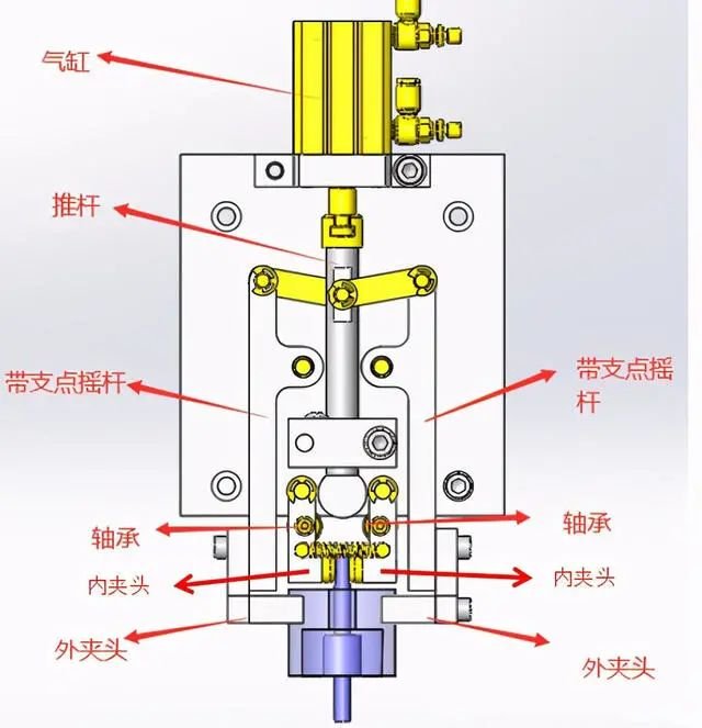

1. When the cylinder extends, the push rod moves down, causing the rotation pivot to rotate. Left and right swing rockers open from both sides. The convex circle in the front section of the push rod clamps the chuck inside the. bearing to open.
2. When the cylinder retracts, the push rod rises, pulling the support rocker to rotate, the outer chuck clamps the large material, the convex ball at the front end of the push rod moves back, the convex ball leaves the bearing and the inner mandrel tighten under spring tension.
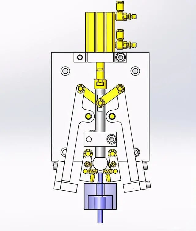

The diagram is only used for reference in principle to give an idea. If design is required, it should be designed according to the specific situation.
This completes the explanation of mechanical design and you are welcome to add to it.
Daguang focuses on providing solutions such as precision CNC machining services (3-axis, 4-axis, 5-axis machining), CNC milling, 3D printing and rapid prototyping services.


